EasyManua.ls Logo

T&M Performance SA 20 User Manual

T&M Performance SA 20
8 pages
To Next Page IconTo Next Page
Page #1 background imageLoading...
Page #1 background image
V12/2009
2:1(560$18$/
%HIRUHDWWHPSWLQJWRFRQQHFWRSHUDWHRUDGMXVWWKLVSURGXFWSOHDVHUHDGWKLVPDQXDOILUVW
WP
3HUIRUPDQFH
6$
32: (5
&+ $ &+ %
3527
&/,3
G%
6,*1$/
$&7,9(
&+ %




 G%


&+ $




 G%


6$
32:(5
&+ $ &+ %
3527
&/,3
G%
6,*1$/
$&7,9(
&+ %




 G%


&+ $




 G%


6$
32: (5
&+ $ &+ %
3527
&/,3
G%
6,*1$/
$&7,9(
&+ %




 G%


&+ $




 G%


6$
32: (5
&+ $ &+ %
3527
&/,3
G%
6,*1$/
$&7,9(
&+ %




 G%


&+ $




 G%


2-channel power amplifi ers
Owner´s Manual
t&mPerformance
Question and Answer IconNeed help?

Do you have a question about the T&M Performance SA 20 and is the answer not in the manual?

T&M Performance SA 20 Specifications

General IconGeneral
Frequency Response20Hz - 20kHz
Total Harmonic Distortion0.1%
Input Impedance47k Ohms
Power Output20W RMS per channel into 8 Ohms
Signal-to-Noise Ratio>90dB (A-weighted)

Summary

Block Diagram

Front Panel View and Controls

Rack Ears

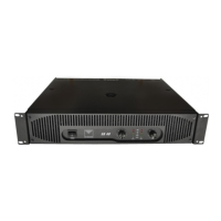
Mounting hardware for rack installation.

Air Intake

Ventilation openings for cooling the unit.

Protect LED

Indicates amplifier protection circuit status.

Signal Presence LED

Indicates presence of an input signal.

Clip LED

Indicates signal clipping, signal distortion.

Active LED

Indicates that the amplifier is actively processing.

-6 dB Level LED

Indicates a signal level at -6 dB.

Power Switch

Main switch for turning the unit on or off.

Channel A Volume Control

Adjusts the audio output level for Channel A.

Channel B Volume Control

Adjusts the audio output level for Channel B.

Rear Panel View and Controls

Cooling Fans

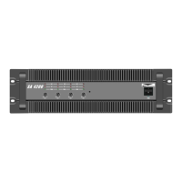
Fans for dissipating heat from the unit.

XLR-f Inputs

Balanced audio input connectors.

XLR-m Link Outputs

Parallel outputs for signal linking.

Speaker Outputs CH A and B

Connectors for speaker system connection.

Bridge Mode Speaker Output

Output connector for bridged mono operation.

Mains Fuse Holder

Compartment for the main power fuse.

IEC Main Power Connector

Socket for connecting the AC power cord.

Ground-Lift Switch

Switch to isolate chassis ground from earth.

Operational Mode Dip Switches

Switches to select amplifier operation mode.

Sensitivity Dip Switches

Switches to set input sensitivity levels.

Limiter Switch

Engages the audio signal limiter function.

Technical Specifications

EU Declaration of Conformity

Operating Instructions

Power Supply Requirements

Specifies AC voltage and frequency for operation.

Mode Selection

Configuring amplifier operation modes via dip switches.

Stereo Mode Operation

Explanation of independent channel operation.

Parallel Mode Operation

Using a single input for both channel outputs.

Bridged Mono Mode Operation

Combining channels for increased power output.

Dust Filter Maintenance

Instructions for cleaning or replacing the dust filter.

Safety Instructions

General Safety and Handling

Covers general usage, environmental, handling, and maintenance safety.

Electrical Safety and Grounding

Addresses power supply connections, voltage, and grounding requirements.

Amplifier Output Usage Rules

Guidelines for connecting amplifier outputs to other devices.

Servicing and Damage Handling

Procedures for servicing and handling damaged apparatus.

Related product manuals