18 CVS Series Quick Start Guide 19
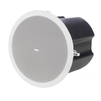
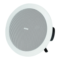
Painting
If desired, the grille and ba e panel may be painted to match the surrounding décor.
Painting the ba e:
• Carefully mask o the driver assembly using the paint-mask provided to ensure that the paint does not come into contact with the cone and roll surround
• Apply several thin coats of paint – this will provide a better nish than one overly thick coat
Painting the grille:
• Carefully remove the acoustically transparent foam from the reverse side of the grille
• Paint the grille and then replace the foam - several thin coats of paint will provide a better nish than one overly thick coat
• Re-bond the foam to the grille over the entire area using a light spray-adhesive to avoid audible resonances
CVS 8 CVS 6 CVS 4 CVS 4 MICRO
System
Frequency response (-3 dB) 79 Hz - 21 kHz 79 Hz - 21 kHz 85 Hz - 19 kHz 110Hz - 19kHz
Frequency response (-10 dB) 60 Hz - 24 kHz 60 Hz - 24 kHz 77 Hz - 22 kHz 90Hz - 22kHz
System Sensitivity (1 W @ 1 m) 93 dB (1 W = 2.45 V for 6 Ohms) 91 dB (1 W = 2.45 V for 6 Ohms) 87 dB (1 W = 2.45 V for 6 Ohms)
Nominal Coverage Angle 90 degrees conical 90 degrees conical
Coverage Angle (1 kHz to 6 kHz) 84 degrees conical 93 degrees 102 degrees
Directivity Factor (Q) 14.7 averaged 1 kHz to 6 kHz 7.7 averaged 1 kHz to 6 kHz 5.6 averaged 1 kHz to 6 kHz
Directivity Index (DI) 11.7 averaged 1 kHz to 6 kHz 8 averaged 1 kHz to 6 kHz 7.1 averaged 1 kHz to 6 kHz
Rated Maximum SPL
111 dB (average)
117 dB (peak)
109 dB (average)
115 dB (peak)
103 dB (average)
109 dB (peak)
Power Handling
Average
Programme
Peak
60 W
120 W
240 W
60 W
120 W
240 W
40 W
80 W
160 W
Recommended Ampli er Power 120 W @ 6 Ohms 120 W @ 6 Ohms 80 W @ 6 Ohms
Nominal Impedance 6 Ohms 6 Ohms 6 Ohms
Transformer Taps (via front rotary switch)
70 V
100 V
60 W / 30 W / 15 W / 7.5 W / OFF &
low impedance operation
60 W / 30 W / 15 W / OFF &
low impedance operation
60 W / 30 W / 15 W / 7.5 W / OFF &
low impedance operation
60 W / 30 W / 15 W / OFF &
low impedance operation
30 W / 15 W / 7.5 W / 3.75 W / OFF &
low impedance operation
30 W / 15 W / 7.5 W / OFF &
low impedance operation
15 W / 7.5 W / 3.75 W / 1.9 W / OFF &
low impedance operation
15 W / 7.5 W / 3.75 W / OFF &
low impedance operation
Transducers
Low Frequency
Coaxial 200 mm (8.00") mineral loaded
cone material
150 mm (6.00") mineral loaded
polypropylene ICT™
100 mm (4.00") mineral loaded cone material
High Frequency 19 mm (0.75") 19 mm (0.75") 19 mm (0.75")
Physical
Enclosure
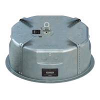
Back can
Ba e
Grille
Zinc plated steel
Re ex loaded UL 94V-0 rated ABS
Steel, with weather resistant coating
Zinc plated steel
Re ex loaded UL 94V-0 rated ABS
Steel, with weather resistant coating
Zinc plated steel
| Painted steel
Re ex loaded UL 94V-0 rated ABS
Steel, with weather resistant coating
Safety Features
Safety ring located at rear of enclosure
for load bearing safety bond
Safety ring located at rear of enclosure
for load bearing safety bond
Safety ring located at rear of enclosure for load bearing safety bond
Clamping Design Security toggle clamp Security toggle clamp Security toggle clamp
Back Can Options
Cable Entry Options
Cable clamp & squeeze connector for
conduit up to 22 mm
Cable clamp & squeeze connector for
conduit up to 22 mm
Cable clamp & squeeze connector for conduit up to 22 mm
Connectors
Removable locking connector
with screw terminals with
“loop through” facility
Removable locking connector
with screw terminals with
“loop through” facility
Removable locking connector with screw terminals with “loop through” facility
Safety Agency Ratings UL-1480, UL-2043, CE UL-1480, UL-2043, CE UL-1480, UL-2043, CE
Hole Cutout Diameter 320 mm (12.60") 250 mm (9.84") 180 mm (7.08")
Dimensions Bezel diameter 355.6 mm (14.00") 279.5 mm (11.01") 213.0 mm (8.39")
Front of ceiling to rear of back can 251.0 mm (9.88") 246.5 mm (9.70") 98.3 mm (3.87") 202.5 mm (7.97")
Front of ceiling to top of safety loop 264.0 mm (10.39") 258.5 mm (10.18") 46.5mm (1.83") 214.9 mm (8.46")
Net Weight (ea) 6.6 kg (14.6 lbs) 5.7 kg (12.6 lbs) 3.6 kg (7.9 lbs) 2.8 kg (6.2 lbs)
Included Accessories
C Ring, tile bridge, paint mask,
cutout template, grille
C Ring, tile bridge, paint mask,
cutout template, grille
C Ring, tile bridge, paint mask, cutout template, grille
Optional Accessories Plaster (mud) ring Plaster (mud) ring Plaster (mud) ring
Notes
(1) Average over stated Bandwidth. Measured in an IEC ba e in an Anechoic Chamber
(2) Unweighted Pink noise input, measured at 1 m on axis
(3) Long term power handling capacity as de ned in EIA - 426B test
Technical Speci cations
 Loading...