This document serves as an Operator's Manual and Parts Breakdown for Tar River Equipment's TXG, YCT, and RXT Rotary Tillers, manufactured by Belco Resources Equipment. The manual provides essential information for the safe and effective operation and maintenance of these agricultural implements.
Function Description
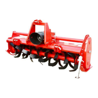
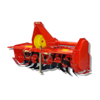
The Tar River Equipment Rotary Tillers are designed for soil preparation in agricultural settings. They are primarily used with 540 rpm tractors to break up and aerate soil, preparing seedbeds for planting. The tillers feature a rotating shaft with blades that cut and mix the soil, improving its structure and promoting better crop growth. The manual emphasizes the importance of maintaining all safety guards and shields to ensure safe operation.
Important Technical Specifications
PTO Shafts:
The manual details specific PTO shaft configurations for different tiller models, primarily distinguishing by series and slip clutch size:
- TXG All sizes: Series 40, equipped with a 150mm slip clutch.
- YCT-60-66-74: Series 40, equipped with a 180mm slip clutch.
- YCT-082 (EARLY): Series 60, equipped with a 180mm slip clutch.
- YCT-082 (LATE): Series 40, equipped with a 180mm slip clutch.
- RXT All Sizes: Series 60, equipped with a 200mm slip clutch.
PTO Driveline Shortening:
When attaching the tiller, it is crucial to ensure the PTO driveline does not bottom out at maximum lift height. If shortening is necessary, the inner and outer guard tubes and profiles should be shortened equally, leaving approximately ½" from the end of the telescopic profiles. A minimum overlap of 1/3 the length of each profile is required for proper function.
Slip Clutches:
The tillers are equipped with slip clutches to protect the PTO and tractor from overload. These clutches can become hot during operation and should not be touched. They have adjustable torque settings, and all springs should have an equal amount of compression. Over-tightening compression nuts can impair performance or cause premature wear.
Oil Levels:
- Top gearbox: Oil level should be 1 1/2" from the end of the dipstick.
- Side gearbox: When slightly tilted forward, oil should be at the bottom of the fill plug on the side gearbox cover.
Usage Features
Safety Guidelines:
The manual stresses the importance of reading and understanding all safety signs and instructions before operation and maintenance. It highlights the safety alert symbol (!) to draw attention to critical safety information. Key safety guidelines include:
- General Safety: Replacing unreadable safety decals, avoiding operation under the influence of drugs or alcohol, reviewing safety instructions annually, and ensuring only responsible, trained adults operate the equipment.
- Before Operation: Carefully studying the manual, wearing appropriate protective clothing and substantial shoes, checking tire inflation, inspecting for loose bolts, worn parts, or cracked welds, and ensuring the area is clear of children and animals.
- During Operation: Not allowing children or bystanders near the product, securely attaching the feeder with a hardened pin and safety chains, using a lower gear on steep downgrades, complying with local and state transport regulations, being aware of bystanders (especially children), and never carrying passengers on the tractor or equipment. Operators should keep hands and clothing clear of moving parts, avoid cleaning or adjusting the equipment while moving, and always set brakes, disengage PTO, shut off the engine, and remove the ignition key when halting operation.
- Highway and Transport Operations: Adopting safe driving practices, using independent braking, maintaining safe speeds, reducing speed on turns and uphill, keeping the tractor in gear on downgrades, and ensuring lights and slow-moving signs are clean and visible. Operators should watch for overhead and side obstructions, maintain maximum visibility, choose the levelest possible route, be careful on inclines, and avoid overhead wires, loose fill, rocks, and holes.
Attaching to the Tractor:
- Position the rotary tiller on a level surface.
- Back the Cat. 1 tractor to align lift arms with the tiller's lower hitch pins.
- Insert lower hitch pins through hitch blocks and tractor arms, securing with a lynch pin or fastener. YCT series tillers have adjustable hitch blocks for larger tractors.
- Repeat for the other arm.
- Connect the driveline to the tractor's PTO output shaft and secure it.
- Connect the tractor top link to the tiller's upper hitch point.
- Start the tractor and slowly raise the tiller, checking for drawbar interference and ensuring the PTO driveline does not bottom out. Shorten the PTO driveline if necessary, ensuring a minimum 1/3 overlap of each profile.
Working Depth Adjustment:
The working depth is controlled by raising or lowering the side skids. Raising the skids increases working depth, while lowering them decreases it.
Tailgate Adjustment:
The tailgate can be adjusted to help smooth and compact the tilled ground. Chains and securing devices are used to set the desired height.
Start Up:
Before starting, make necessary adjustments, lower the rotary tiller until the blades are a couple of inches from the ground, engage the PTO, and slowly lower the tiller to begin working.
Removal and Storage:
After finishing operation, remove the rotary tiller from the tractor. This involves putting the PTO driveline in a safe location, cleaning and drying the equipment, replacing any damaged or worn parts, checking all bolts and nuts for tightness, and lubricating and protecting the machine from the elements.
Maintenance Features
Performing Maintenance:
The manual provides a maintenance schedule to ensure the tiller's longevity and safe operation:
- Good Maintenance: Emphasizes that good maintenance is crucial for preventing trouble.
- Ventilation: Ensure proper ventilation when operating the engine of the towing vehicle in an enclosed building to avoid carbon monoxide poisoning.
- Before Maintenance: Allow the machine to cool down completely before performing maintenance.
- Tools: Always use proper tools and equipment.
- Hex Bolts: Never replace hex bolts with less than grade five bolts unless otherwise specified.
- After Servicing: Ensure all tools, parts, and service equipment are removed.
- Replacement Parts: Use only genuine factory replacement parts to maintain warranty and ensure proper fit and function.
- Modifications: The manufacturer does not accept liability for injury or warranty if equipment has been altered from its original design.
Maintenance Schedule:
- 8 hours:
- Grease the Rotor support (GP grease).
- Grease PTO shaft cross & bearings (GP grease).
- Check Hardware for tightness.
- 16 hours:
- Check oil level in center gearbox (90wt).
- Check oil level in side gearbox (140wt).
- Check Hardware for tightness.
- 200 hours:
- Replace oil in center gearbox (90wt).
- Replace oil in side gearbox (140wt).
- Change chain tensioner spring (DLT model only).
- Check Hardware for tightness.
Replacing Blades:
To optimize performance, ensure tiller blades are in good working condition. Always replace blades with the bolt head against the blade and the washer and nut on the flange side to prevent the blades from loosening. When several blades are to be replaced, replace them one blade at a time to maintain the scroll pattern on the rotor. For identification, the blade by the bolt hole end and the cutting edge facing downward is a left-hand blade, while the opposite configuration is a right-hand blade.
Limited Warranty:
- Standard Warranty: One (1) year for non-commercial, state, and municipalities' use; ninety (90) days for commercial use; thirty (30) days for rental purposes from the date of retail sale. Covers defects in material and workmanship, limited to repair or replacement of defective parts.
- Extended Gearbox Limited Warranty: A four (4) year extended warranty for YCT & RXT models, beginning after the standard one-year warranty period. This applies only to parts replacement and does not cover commercial or rental uses, oil seals, or damage due to lack of lubrication.
- Replacement Parts Warranty: Ninety (90) days from purchase or until the expiration of the applicable new equipment warranty period, whichever is later. Parts are provided at no cost by an authorized Tar River Equipment dealer during regular working hours.
- Exclusions: Wear items (shear pins, tires, tubes, knives, blades) and oil/grease are not covered.
- Termination: Warranty is terminated if proper service is not performed, the machine is modified or altered, or used for purposes other than intended.
- Disclaimer: Tar River Equipment's obligation is limited to warranties, implied or expressed, including merchantability and fitness for a particular purpose, and any liability for incidental and consequential damages (transportation charges, installation costs, duty, taxes, service/adjustment charges, loss).
The manual includes detailed parts breakdowns for the TXG, YCT, and RXT models, with exploded diagrams and corresponding part lists, including position numbers, part numbers, descriptions, and quantities. This comprehensive guide ensures operators can identify and order the correct components for maintenance and repair.