©Copyright Task Force Tips, Inc. 2004-2009 LIA-202 October 20, 2009 Rev01
3
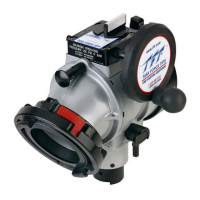
4.0 RELIEF VALVE FLOW vs. PRESSURE CURVE
0
25
50
75
100
125
150
175
200
225
250
275
300
0 25 50 75 100 125 150 175 200
FLOW (GPM)
PRESSURE (PSI)
0
5
10
15
20
0 100 200 300 400 500 600 700
FLOW (LPM)
125 PSI SETTING
200 PSI SETTING
50 PSI SETTING
PRESSURE (BAR)
PRESSURE RELIEF VALVE PERFORMANCE
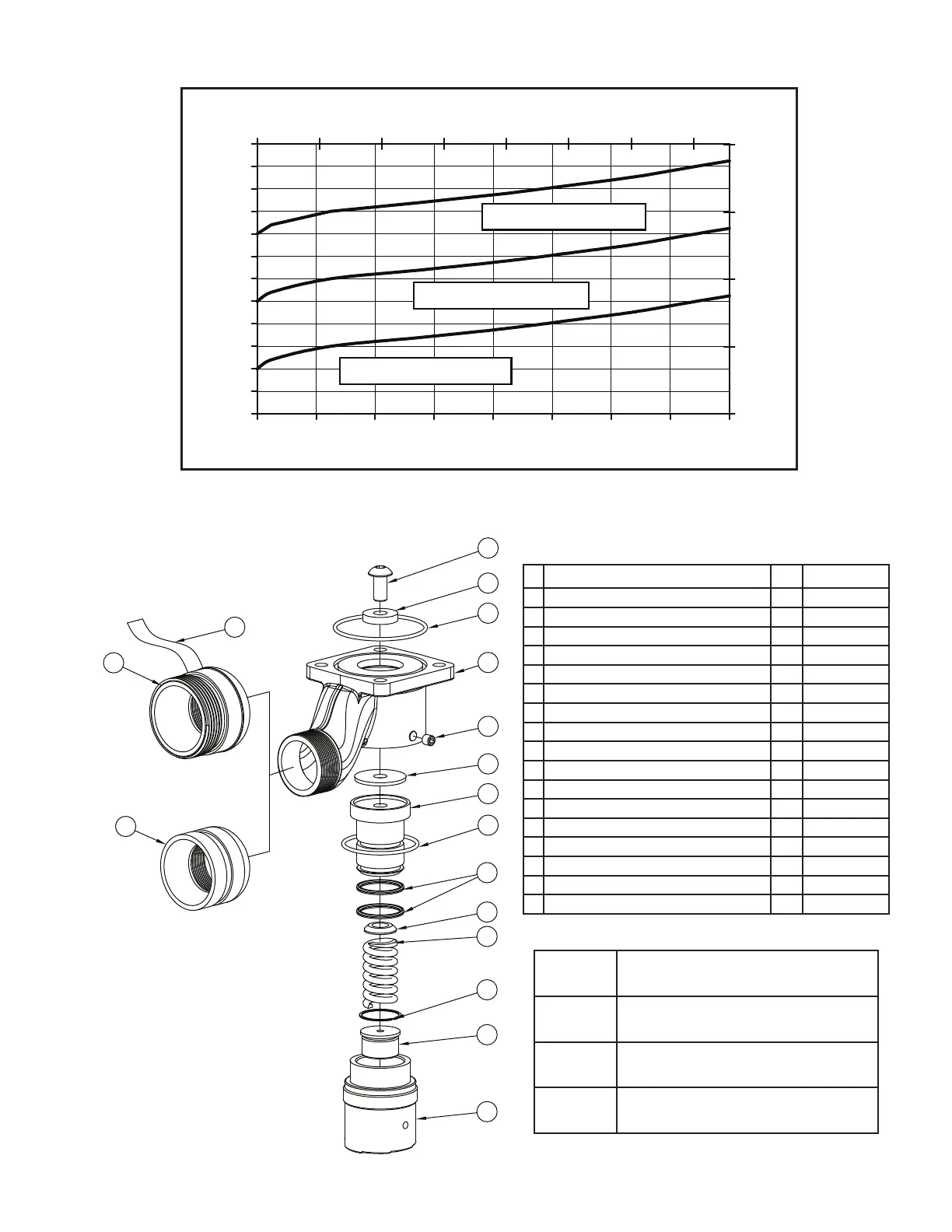
5.0 DRAWING AND PARTS LIST
15
14
13
12
11
9
8
7
4
2
3
1
6
5
17
16
18
Pressure Relief Valve 50 - 200 PSI
DESCRIPTION
QTY
PART #
1 1/2-13 X 1.0 Button Head Cap Screw 1 VT50-13BH1.0
2 O-RING-236 3-1/4 ID 1/8 C/S 1 VO-236
3 Debris Washer 1 A1169
4 HOUSING W/OUT THDS 1 A1150***
5 5/16-18 X 3/8 Socket Set Screw Cup Point 1 VT31-18SS375
6 Valve Seat 1 A1168
7 Piston -Hardcoat 1 A1160
8 O-RING-231 2-5/8 ID 1/8 C/S 1 VO-231
9 QUAD RING 422 1.5 ID X 1/8 C/S 2 VOQ-4222
11 Spring Seat 1 A1166
12 Relief Spring 1 A1170
13 Smalley Ring 1 V4210
14 Adjusting Screw 1 A1167
15 Spring Housing 1 A1164
16 PRV Adaptor 2.0"NPT X 2.5" Victaulic 1 A1851-1
17 PRV Adaptor 2.0"NPT X 2.5"NH 1 A1861-1
18 PRV “DO NOT CAP” Label 1 A1865L
*** Index 4 Housing Choices
A1150 Housing with Waterous / Hale hole pattern.
(TFT Standard) Plain discharge.
A1150PH Housing with Waterous / Hale hole pattern.
2” NPT male discharge.
A1151 Housing with Darley hole pattern.
Plain discharge.
A1151PH Housing with Darley hole pattern.
2” NPT male discharge.
 Loading...