This document is a user installation reference guide for the Tate Grid: Ceiling System, Rev. 1, 2/2022. It provides instructions and guidelines for the proper installation, safety, cleaning, and connection of the ceiling grid components.
Function Description
The Tate Grid: Ceiling System is a modular ceiling grid designed for supporting various ceiling elements. It consists of main runners, cross tees, and various connectors that form a robust framework. The system is designed to be suspended from above, allowing for the integration of lighting, HVAC, and other building services. The guide details how to assemble these components to create a stable and aligned ceiling structure.
Important Technical Specifications
- Bolt Torque: All bolt connections to the top slot of the grid should be tightened flush to a washer with a maximum torque value of 30 in-lb. Similarly, all bolt or nut connections to the bottom slot of the grid should be tightened flush to a washer or mounting bracket with a maximum torque value of 30 in-lb. This ensures secure connections without over-tightening.
- Thread Engagement: When threading bolts or threaded rod into the bottom slot to hang equipment, it is crucial that the bolt or rod is long enough to fully engage the depth of the slot entirely. The guide warns that less than 75% engagement could lead to thread tear-out at loads below the system's rated capacity.
- Lock Washers: For bolts or threaded rods secured into the bottom slot, a nut and lock washer must be used to prevent loosening due to vibration over time, ensuring long-term stability of hung equipment.
- Component Part Numbers (PN):
- Turnbuckle & Starter Rod: PN28361
- XL Connector: PN22297
- Field Connector: PN22293
- Perimeter Connector: PN22295
- 1/4"-20 Screw: PN23077
- 1/4" Lock Washer: PN23078
These part numbers are essential for identifying and ordering the correct components for installation and maintenance.
Usage Features
- Modular Design: The system uses main runners and cross tees to create a grid, typically for 2'x2' configurations, allowing for flexible layout and easy integration of ceiling panels or other fixtures.
- Main Runner Alignment: Main runners are not symmetric and must be oriented in the same direction throughout the installation to ensure proper grid alignment. A "NOTCH Q" is indicated on the diagram, likely serving as an alignment indicator.
- Cross Tee Alignment: For 2'x2' grid systems, 4' tees should be installed first between the main runners. Witness notches at the ends of the 4' tees must all be oriented in the same direction to ensure that the 2' tees align properly and parallel to the main runners.
- Main Runner Splice Connectors: Main runners come with a steel splice connector inserted at one end from the factory. This connector is designed to be inserted into the opposite end of the next main runner and then bolted together using an XL connector and eight screws and lock washers, creating a continuous main runner.
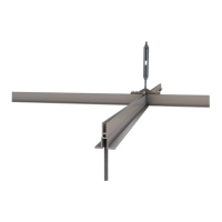
- Suspension Points: The system utilizes turnbuckle and starter rods (PN28361) for suspension. These can be connected at the joints of main runners using an XL connector (PN22297) or mid-main runner using a field connector (PN22293). Both connections require 1/4"-20 screws (PN23077) and 1/4" lock washers (PN23078).
- Structural Tee Connections: Structural tees are connected using a field connector (PN22293), 1/4"-20 screws (PN23077), and 1/4" lock washers (PN23078).
- Perimeter Connections:
- Perimeter Intersection: At corners or intersections along the perimeter, a perimeter connector (PN22295) is used. For these specific intersections, two legs of the connector need to be removed in the field. Connections are secured with 1/4"-20 screws (PN23077) and 1/4" lock washers (PN23078).
- Perimeter & Structural Tee/MR Intersection: Where the perimeter meets a structural tee or main runner, a perimeter connector (PN22295) is also used, but only one leg needs to be removed in the field. This connection also uses 1/4"-20 screws (PN23077) and 1/4" lock washers (PN23078).
Maintenance Features
- Cleaning: Tate Grid components can be cleaned using a common non-abrasive mild detergent containing less than 0.5% phosphate and water, applied with a sponge. Components should be dried with a soft towel.
- Solvent Use: For removing materials not soluble in water (e.g., petroleum products), the following solvents can be used: Isopropyl alcohol, denatured alcohol, mineral spirits, or methanol. This provides options for more stubborn stains while protecting the material.
- Regular Inspection: Although not explicitly stated as a maintenance feature, the emphasis on proper torque, thread engagement, and lock washers implies the importance of regular inspection to ensure all connections remain secure and prevent loosening over time due to vibration or other factors.
Safety Features
- Personnel Requirement: The guide explicitly states that "2 or more people are required for handling some of the pieces for this system," highlighting the need for teamwork and safe lifting practices.
- Personal Protective Equipment (PPE): Users are instructed to "Wear personal protective equipment (PPE) when drilling, cutting, or installing. PPE includes gloves, safety eyeglasses, hardhats, etc." This emphasizes worker safety during the installation process.
- Load Bearing: A critical safety instruction is "Do not put a load on the system until the installation is complete." This prevents premature loading that could compromise the integrity of an incomplete structure.
- Tightening of Fasteners: The guide stresses, "Be sure all bolts, nuts, and threaded rods are properly tightened down as described in this guide," reinforcing the importance of secure connections for the overall safety and stability of the ceiling system.