18
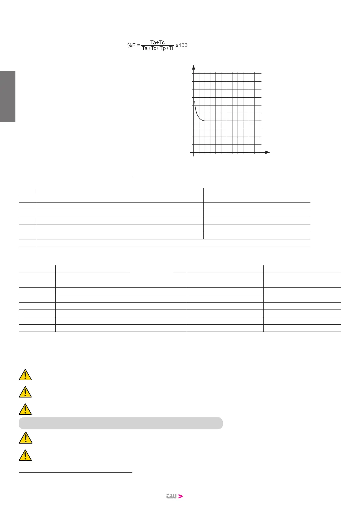
Important: the curve is obtained at a temperature of 15 °C.
Exposure to direct sunlight may reduce the frequency of use by up to 20%
Calculating the frequency of use:
This is the percentage of the eective operating time (opening and closing) with respect to the total time of the cycle (opening + closing + pause time).
The calculation formula is as follows:
where:
Ta = Opening time
Tc = Closing time
Tp = Pause time
Ti = Interval time between one complete cycle and the next
Percentuale
di lav. %
% Frecuencia
de utilización
% factor
serviço
% Fréquence
d’utilisation
% Benutzungs-
frequenz
% Duty cycle
Tempo (h) Time (h) Zeit (Std.)
Temps (h)
Tiempo (h) Tempo (h)
1 0
10
100
90
80
70
60
50
40
30
20
2 3 4 5 6 7 8 9 10 11 12
2.2_ Typical system
Figure 3 shows a typical automation system for a sliding gate using T-ONE.
N° Description N° Description
1 Key-operated selector switch 8 Flashing light with built-in aerial
2 Fixed primary edge (optional) 9 Gearmotor
3 Photocells 10 “Closed” limit switch bracket
4 Mobile primary edge 11 Wireless system
5 “Open” limit switch bracket 12 Floor-mounted end stops
6 Rack 13 Secondary mobile edge (optional)
7 Secondary xed edge (optional)
Wiring:
The typical system in gure 3 also shows the cables required for connecting the various devices; the table species the cable specications.
Connection Cable type Ref. 230 V AC 12 V DC
a: Mains power line a 3x1,5mm² 3x1,5mm²
b: Flashing light b 2x0,5mm² 2x0,5mm²
c: Antenna c RG58 RG58
d: Photocells (TX) d 2x0,5mm² (TX) 2x0,5mm² (TX)
e: Photocells (RX) e 4x0,5mm² (RX) 4x0,5mm² (RX)
f: Key-operated selector switch f* 3x0,5mm² 3x0,5mm²
g: Primary sensitive edge g 2x0,5mm² 2x0,5mm²
h: Mobile edges h 2x0,5mm² 2x0,5mm²
* If art. P-300TSL is also installed, envisage a cable 5x0.5 mm for the key selector switch.
Notes:
• If the power cable is longer than 30 m, a cable with a larger cross-section is required (3 x 2.5 mm2) and safety earthing is necessary in the vicinity of
the automation.
Place the control unit (external versions) in the immediate vicinity of the motors.
Be careful not to run cables for auxiliary devices inside raceways housing other cables supplying power to large loads or lights
with electronic starters.
In the event control pushbuttons or indicator lights are installed inside homes or oces several metres from the actual control
unit, it is advisable to decouple the signal by means of a relay in order to avoid induced interference.
3. INSTALLATION
T-ONE must be installed by qualied personnel, in compliance with local legislation, standards, regulations and these instructions.
Use on gates with a gradient or slope is NOT allowed.
3.1. Preliminary checks
Before installing T-ONE, perform the following checks:
• Ensure that all material used is in perfect condition, suitable for use and compliant with standards.
• Ensure that the gate structure is suitable for automation.
ENGLISH
 Loading...