11
Owner’s Manual
COMPACT TILLER AND CULTIVATOR
Get parts online at www.tazzoutdoorproducts.com or Call 800-345-6007 M-F 8-5 CST
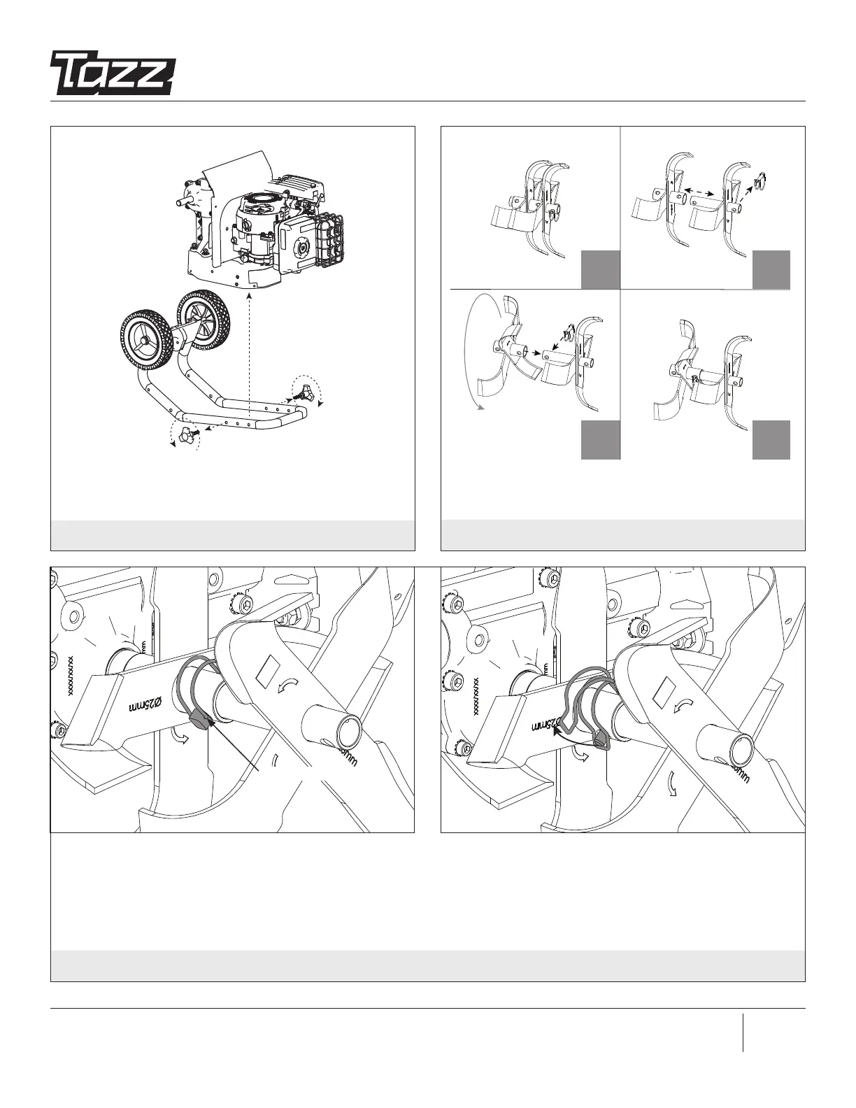
FIGURE 4
Remove hand knob bolts from both sides of tiller. Separate
lower handlebar assembly from pulley box and cut zip ties
to remove handlebars.
FIGURE 5
Remove lock pin from one tine set. Slide outer tine and
rotate to align with the second hole position of inner tine,
then secure with lock pin. Repeat for other tine set.
a
c d
d
c
b
LOCK PIN INSTALLED CORRECTLY
LOCK PIN HINGE
NOTE: Ensure the lock pins and tines are correctly installed. Lock pins must be installed so that the pin enters the hole in the
tine from the front of the tiller, and so the wire bale hinges over the top of the tine pipe and latches to the protruding pin on
the back side of the tine. Tines can inadvertently detach during tilling if lock pins are not installed correctly!
FIGURE 5A
LOCK PIN INSTALLED INCORRECTLY