4 Twin City IM-4800
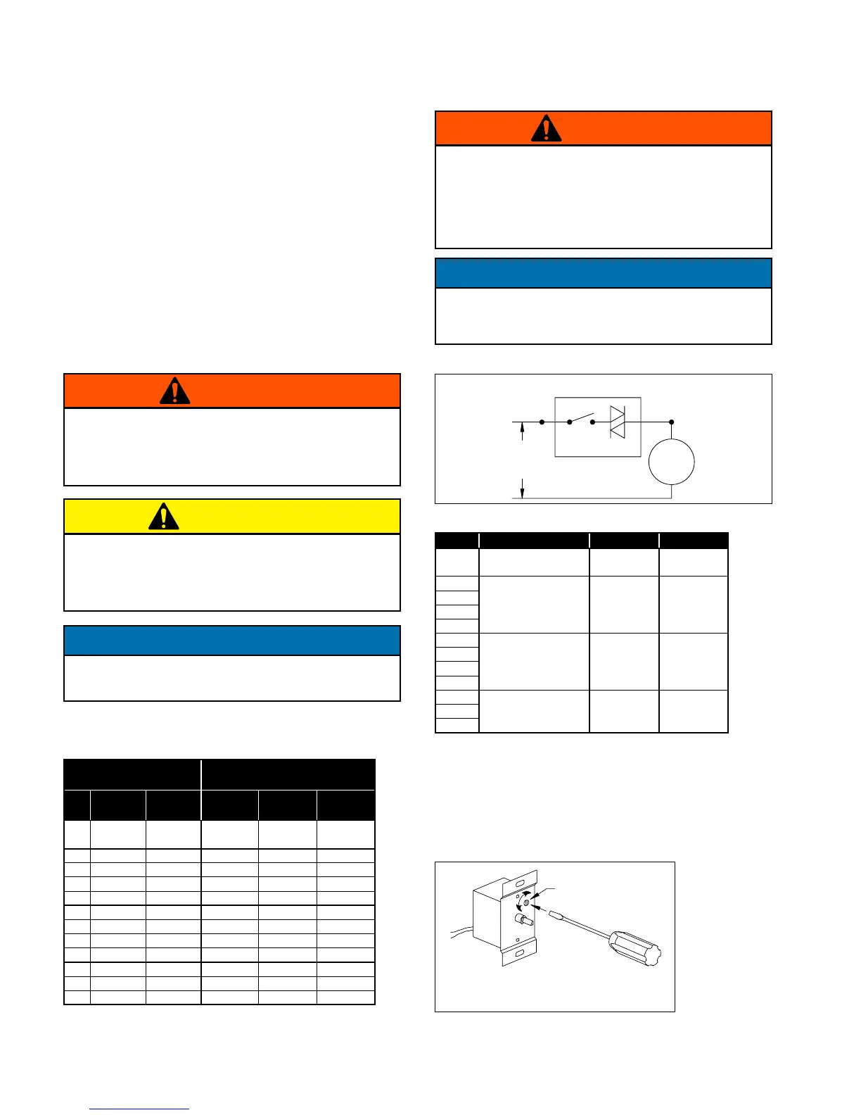
Figure 2. Low End Setpoint Adjustment
NOTE: 5 amp model shown. On 10 and 15 amp
models, adjustment is made through clearance
hole in heat sink.
SETPOINT
ADJUSTMENT
SCREW
Table 1. Speed Controller Size
MOTOR
SPEED CONTROLLER
DESIGNATION / FLA
HP RPM VOLTAGE
KBWC-15K
5 AMP
KBWC-110
10 AMP
KBWC-115
15 AMP
1/8
1650/1500/
1350
115V X
1/8 860 115V X
1/6 860 115V X
1/4 860 115V X
1/2 860 115V X
1/6 1140 115V X
1/4 1140 115V X
1/2 1140 115V X
1 1140 115V X
1/3 1725 115V X
1/2 1725 115V X
3/4 1725 115V X
Speed Control Installation
(Model TCPE - optional)
The controller is designed to start the motor at high
speed and will then slow down. This gives the motor
good starting characteristics.
Speed control is available using 115/60/1 open type
PSC or shaded pole motors.
Installation
Connect control in series with motor and line voltage
(115V only). Never connect across line. See Figure 1.
Minimum Speed Setpoint
All controls are factory set to 65V±3V output as standard
with an input voltage of 120V. If different minimum
speed is desired, the control may be adjusted by turning
minimum speed pot clockwise to decrease minimum
speed and counterclockwise to increase minimum speed.
Refer to Figure 2.
NOTE: For TCPE fans using Electronically Commutated
(EC) Motors, refer to IM-4055.
Figure 1. Connection Diagram, Speed Control
SPEED CONTROLLER
AC
LINE
(115V)
SWITCH TRI-AC
MOTOR
Table 2. Speed Controller RPM Range
NOTES:
1. Speed control available only with 115/60/1 open motors (thermally
protected).
2. Three-speed motor (multiple tap winding).
3. Speed control should not be connected to low speed tap on motor
because of starting characteristics.
4. Speed control connected to high speed tap on motor.
5. Speed control connected to medium speed tap on motor.
If minimum speed is readjusted, verify unit ampere
draw does not exceed motor nameplate amps. Do
not operate unit in range where amp draw exceeds
motor nameplate.
WARNING
These motors operate more efficiently in the ranges
set from the factory. Operating motor outside these
ranges (see Table 2) may cause motor to run hotter
and substantially shorten motor life.
CAUTION
Lowering the minimum speed setpoint may adversely
affect motor start-up characteristics.
NOTICE
Certain failure modes of solid-state controls such
as half-waving can cause high levels of DC, motor
overheating and motor burn-out. Therefore, a
thermal overload protection (integral with motor) is
required to limit the maximum motor temperature
under such a failure.
WARNING
Do not allow any sleeve bearing motor to operate
below 500 RPM. Operation below 500 RPM will
substantially shorten bearing life.
NOTICE
HP RPM MAX. RPM MIN. RPM
1/8
1650/1500/1350
2,3
1650
4
1300
4
1500
5
950
5
1/8
860 860 500
1/6
1/4
1/2
1/6
1140 1140 900
1/4
1/2
1
1/3
1725 1725 1200
1/2
3/4
 Loading...