4 Set Up
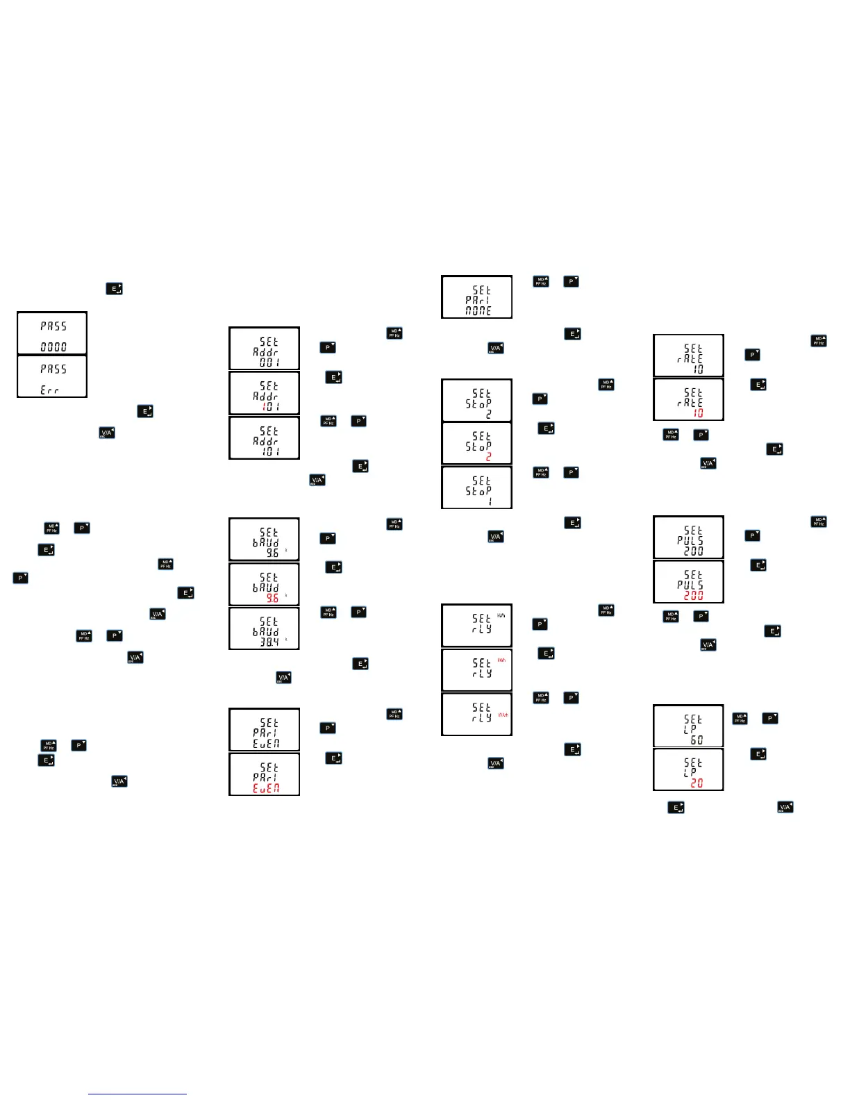
To enter set-up mode, press the button for 3 seconds, until
the password screen appears.
Setting up is password protected
so you must enter the correct
password (default ‘1000’) before
processing.
If an incorrect password is
entered, the display will show:
PASS Err
Once the correct password is entered, hold for 1 second to
enter the setup menu.
To exit the setup menu, press repeatedly until the
measurement screen is restored.
4.1 Set-up Entry Methods
Some menu items, such as password and Modbus address,
require a four-digit number entry while others, such as supply
system, require selection from a number of menu options.
CT ratio is not required. This product is directly connected.
4.1.1 Menu Option Selection
1. Use the and buttons to scroll through the different
options of the set up menu.
2. Press to confirm your selection.
3. If an item flashes, then it can be adjusted by the and
buttons.
4. Having selected an option from the current layer, press
to confirm your selection. The SET indicator will appear.
5. Having completed a parameter setting, press to return to
a higher menu level. The SET indicator will be removed and you
will be able to use the and buttons for further menu
selection.
6. On completion of all setting-up, press repeatedly until
the measurement screen is restored.
4.1.2 Number Entry Procedure
When setting up the unit, some screens require the entering of a
number. In particular, on entry to the setting up section, a
password must be entered. Digits are set individually, from left to
right. The procedure is as follows:
1. The current digit to be set flashes and then can be adjusted
using the and buttons.
2. Press to confirm each digit setting. The SET indicator
appears after the last digit has been set.
3. After setting the last digit, press to exit the number
setting routine. The SET indicator will be removed.
4.2 Communication
There is a RS485 port can be used for communication using
Modbus RTU protocol. For Modbus RTU, parameters are
selected from Front panel.
4.2.1 RS485 Address
From the set-up menu, use
and buttons to select the
address ID.
Press button to enter the
selection routine. The current
setting will be flashing.
Use and
buttons to choose Modbus
address (001 to 247).
On completion of the entry procedure, press button to
confirm the setting and press button to return the main set-
up menu.
4.2.2 Baud Rate
From the set-up menu, use
and buttons to select the
Baud Rate option.
Press to enter the selection
routine. The current setting will
flash.
Use and buttons to
choose Baud rate 2.4k. 4.8k, 9.6k,
19.2k, 38.4k
On completion of the entry procedure, press to confirm the
setting and press to return to the main set up menu.
4.2.3 Parity
From the set-up menu, use
and buttons to select the
parity option.
Press to enter the selection
routine. The current setting will
flash.
Use and buttons to
choose parity (EVEN /
ODD / NONE (default)).
On completion of the entry procedure, press to confirm the
setting and press to return to the main set up menu.
4.2.4 Stop bits
From the set-up menu, use
and buttons to select the
stop bit option.
Press to enter the selection
routine. The current setting will
flash.
Use and
buttons to choose stop bit (2 or 1).
On completion of the entry procedure, press to confirm the
setting and press to return to the main set up menu.
4.3 Pulse Output
This option allows you to configure the pulse output. The output
can be set to provide a pulse for a defined amount of energy
active or reactive. Use this section to set up the relay pulse
output—Units: kWh, kVArh.
From the set-up menu, use
and buttons to select the
Pulse output option.
Press to enter the selection
routine. The unit symbol will flash.
Use and buttons to
choose kWh or kVArh.
On completion of the entry procedure, press to confirm the
setting and press to return to the main set up menu.
4.3.1 Pulse rate
You can configure the pulse output to relate to a defined amount
of imported or exported energy. This can also be set to use with
active energy (kWh) or reactive energy (kVarh).
Please note there are limitations that need to be factored in when
setting the pulsed output. This is based upon the relay output
only being able to pulse 2 times in one second.
Pulse settings: 1 pulse per 0.01(10W) / 0.1(100W) / 1 (1kWh)
/10(10kWh) / 100(100kWh) /1000 (1000kWh).
DFT= Default. Set as 1 (1kWh)
From the set-up menu, use
and buttons to select the
Pulse Rate option.
Press to enter the selection
routine. The current setting will
flash. 0.01/0.1/1/10/100kWh/
kVArh per pulse.
Use and buttons to choose pulse rate. On
completion of the entry procedure, press to confirm the
setting and press to return to the main set up menu.
4.3.2 Pulse Duration (DIT)
The energy monitored can be active or reactive and the pulse
width can be selected as 200, 100 or 60ms (Default).
From the set-up menu, use
and buttons to select the
Pulse width option.
Press to enter the selection
routine. The current setting will
flash.
Use and buttons to choose pulse width. On
completion of the entry procedure press to confirm the
setting and press to return to the main set up menu.
4.4 Light Period (LP)
The light period is a programmable time (in minutes) that
determines how long the display backlight remains on for before
this goes into standby.
From the set-up menu, use the
and buttons to select
the reset option.
Press to enter the selection
routine. The dIt will flash. The
options are 0/10/30/60/120
minutes.
Press to confirm the setting and press to return to
the main set up menu.
 Loading...