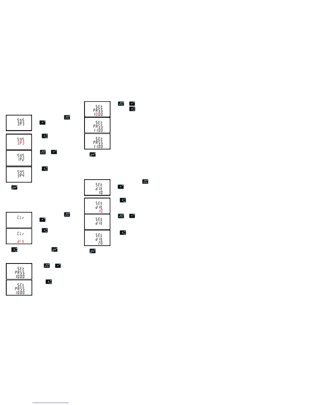
Press to exit the DIT selection routine and return to the
menu.
5 Specifications
5.1 Measured Parameters
The unit can monitor and display the following parameters of a
single phase two wire (1p2w), three phase three wire (3p3w) or
three phase four wire (3p4w) system.
5.1.1 Voltage and Current
• Phase to neutral voltages 100 to 289V a.c.
(not for 3p3w supplies).
• Voltages between phases 173 to 500V a.c.
(3p supplies only).
• Continuous Overload voltage 120%
• Percentage total voltage harmonic distortion
(THD%) for each phase to N ( not for 3p3w
supplies).
• Percentage voltage THD% between phases
(three phase supplies only).
• Current 100A (Direct connected)
• Continuous Overload current 120%
• Current THD% for each phase.
• Burden <10VA (nom 2VA)
• Self powered from any phase
5.1.2 Power factor and Frequency and Max. Demand
• Frequency in Hz
• Instantaneous power:
• Power 0 to 3600 MW
• Reactive power 0 to 3600 MVAr
• Volt-amps 0 to 3600 MVA
• Maximum demanded power since last Demand
reset Power factor
• Maximum neutral demand current, since the last
Demand reset (for three phase supplies only)
5.1.3 Energy Measurements
5.2 Measured Inputs
Voltage inputs through 4-way fixed connector with 2.5mm²
stranded wire capacity. Single phase two wire(1p2w), three
phase three wire(3p3w) or three phase four wire(3p4w)
unbalanced. Line frequency measured from L1 voltage or L3
voltage.
5.3 Accuracy
• Voltage 0·5% of range maximum
• Current 0·5% of nominal
• Frequency 0·2% of mid-frequency
• Power factor 1% of unity (0.01)
• Active power (W) ±1% of range maximum
• Reactive power (VAr) ±1% of range maximum
• Apparent power (VA) ±1% of range maximum
• Active energy (Wh) Class 1 IEC 62053-21
• Reactive energy (VARh) ±1% of range maximum
• Total harmonic 1% up to 31st harmonic
distortion
• Response time to 1s, typical, to >99% of
step input final reading, at 50 Hz.
5.4 Interfaces for External Monitoring
Three interfaces are provided:
• RS485 communication channel that can be
programmed for Modbus RTU protocol
• Relay output indicating real-time measured energy.
(configurable)
• Pulse output 400imp/kWh (not configurable)
The Modbus configuration (baud rate etc.) and the pulse relay
output assignments (kW/kVArh import/export etc.) are configured
through the set-up screens.
5.4.1 Pulse Output
Opto-coupler with potential free SPST-NO Contact
(Contact range 5-27VDC / Max current input: Imin 2mA and Imax
27mA DC). The pulse output can be set to generate pulses to
represent kWh or kVArh.
Rate can be set to generate 1 pulse per:
0.01 = 10 Wh/VArh
0.1 = 100 Wh/VArh
1 = 1 kWh/kVArh
10 = 10 kWh/kVArh
100 = 100 kWh/kVArh
Pulse width 200/100/60 ms.
5.4.2 RS485 Output for Modbus RTU
For Modbus RTU, the following RS485 communication
parameters can be configured from the set-up menu:
Baud rate 2400, 4800, 9600, 19200, 38400
Parity none (default) / odd / even
Stop bits 1 or 2
RS485 network address nnn – 3-digit number, 1 to 247
Modbus™ Word order Hi/Lo byte order is set automatically to
normal as defined by IEEE 754. It cannot be configured from the
set-up menu.
5.5 Reference Conditions of Influence Quantities
Influence Quantities are variables that affect measurement errors
to a minor degree. Accuracy is verified under nominal value
(within the specified tolerance) of these conditions.
• Ambient temperature 23°C ±1°C
• Input waveform 50 or 60Hz ±2%
• Input waveform Sinusoidal (distortion
factor < 0·005)
(if AC) factor < 0·05)
• Magnetic field of Terrestrial flux
external origin
5.6 Environment
• Operating temperature -25°C to +55°C*
• Storage temperature -40°C to +70°C*
• Relative humidity 0 to 95%,
non-condensing
• Altitude Up to 3000m
• Warm up time 1 minute
• Vibration 10Hz to 50Hz, IEC
60068-2-6, 2g
• Shock 30g in 3 planes
*Maximum operating and storage temperatures are in the context
of typical daily and seasonal variation.
5.7 Mechanics
• DIN rail dimensions 76 x 100 mm (WxH)
per DIN 43880
• Mounting DIN rail (DIN 43880)
• Sealing IP51 indoor
• Material UL 94 V-0
Self-extinguishing
6 Installation and Maintenance
6.1 Installation notes
Units should be installed in a dry position, where the ambient
temperature is reasonably stable and will not be outside the
range -25 to +55⁰C.
Vibration should be kept to a minimum.
Preferably, mount the Integra so that the display contrast is not
reduced by direct sunlight or other high intensity lighting.
 Loading...