Names and Parts
1-8
Names and Parts
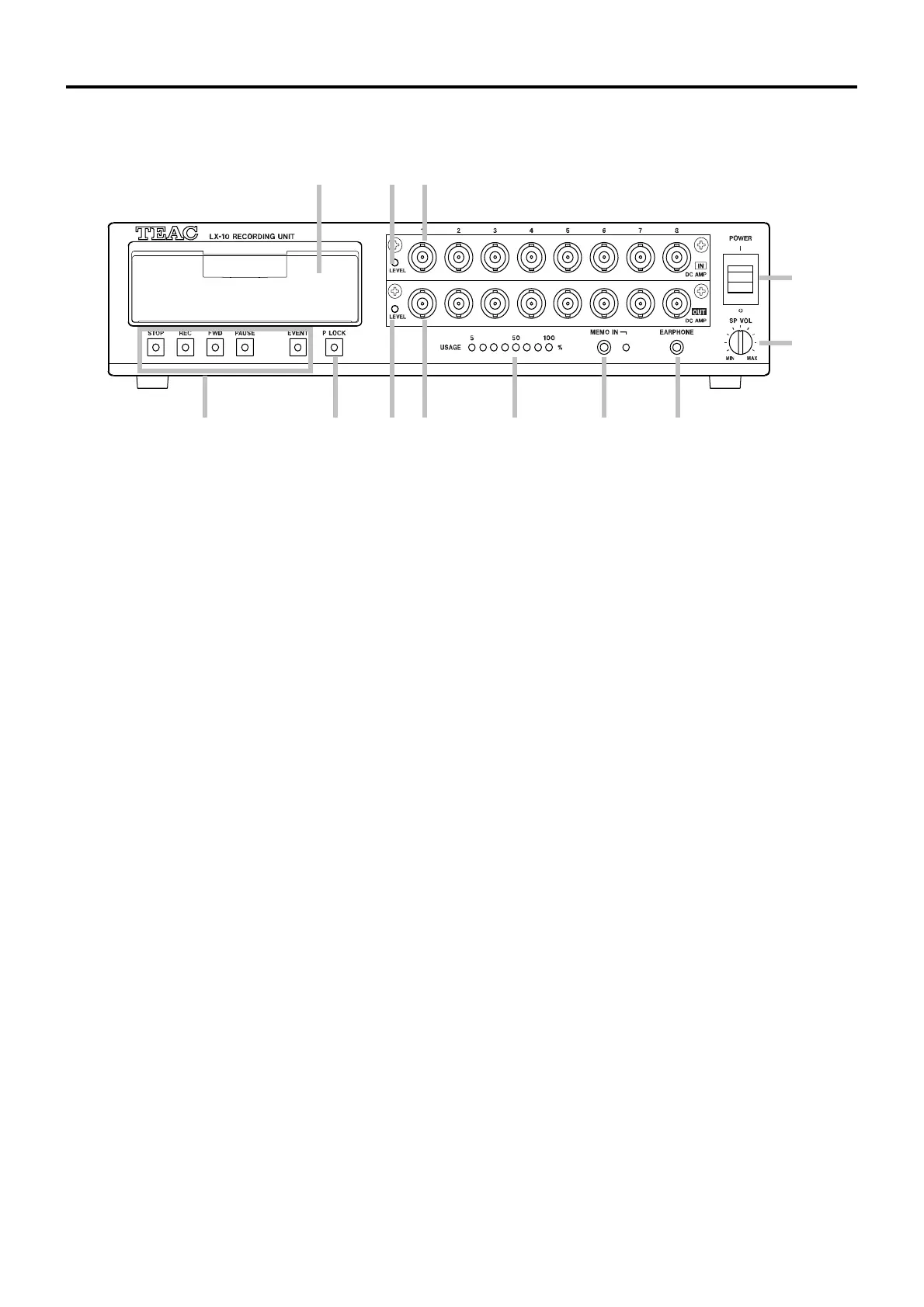
Front
1 Drive
Opening the cover reveals the disk slot.
2 Input level LED
When the input signal for some channel is larger than +/- 10 % of a set input range, the LED glows
green.
When the signal exceeds +/- 115 % of the range, the LED glows red.
3 Input connector
Inputs the signal to be measured.
4 Power switch
Pushing the switch up turns on the power. Pushing the switch down turns off the power.
5 Volume knob
Adjust the volume for reproducing voice memos.
6 EARPHONE jack
Connects to an earphone when you are using the earphone to listen to voice memos.
When an earphone is inserted, sound does not come from the speaker.
7 MEMO IN jack
Connects to a microphone used for voice memos.
8 USAGE LEDs
Indicates the usage rate of the recording device. During recording to memory, these LEDs indicate
what percentage of the total memory is being used. During recording to a media, these LEDs
indicate what percentage of the total media capacity is being used. During recording to a PC, these
LEDs indicate what percentage of memory is being used as the buffer for transmitting data. From
the left, the LEDs indicate the percentages of 5, 10, 20, 35, 50, 70, 90, and 100%.
These LEDs also function as a low-voltage alarm, and blink when the power voltage falls to 11 V or
less. In such a situation, recording or reproduction stops.
1 2 3
5
4
9 8 7 6
10 12 11
 Loading...