7
Solution
1) Identify direction of flow from the tractor and make sure it is directed to the inlet port of the valve. Fitting
of a check valve to the outlet port can prevent reverse flow if the machine is connected incorrectly on a
regular basis.
2) Check the quick release coupling of the return hose is connected correctly.
3) Check the operation and condition of the quick release couplings.
4) Install a free flow return connection to the tractor.
5) Reduce the flow of hydraulic oil to the valve (60 litres max).
6) Check torque of studs holding valve block together (13 Nm, 10 lb ft).
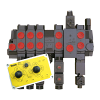
2.5 Oil leaks from the interface between the flow control slice and the adjacent double acting slice
due to the O ring in the Oval recess being missing ( O ring 20 in diagram A).
Solution
On a valve manufactured before 2005 where the seals are being replaced between the flow control slice and
the adjacent double acting slice it may be necessary to fit an additional retaining collar to prevent the O ring
from being extruded - Contact Teagle Machinery Ltd for details
2.6 Oil leak from the cap at the bottom of a valve slice.
Possible causes
Incorrectly fitted seals or seal failure.
Solution
Replace the seals. Remove the cable form the valve slice causing the problem. Unscrew the cap from the bot-
tom of the valve taking care not to lose any springs and detent balls. Remove the spool. Fit the new slip ring
to the spool sliding it down to the bottom of the spool and fitting the O ring outside the slip ring. Insert the
spool back into the valve body making sure the O ring remains outside the slip ring. Reassemble the cable
back onto the spool and refit the cap at the bottom of the valve.
IMPORTANT - To ensure correct and reliable operation, OEM components including O rings must be fitted
during any overhaul of the valve, failure to do so may lead to repeated failures as specific high quality grade O
rings are used to seal the valve.
Remove the hoses from the valve block then remove the valve complete with cables and mounting plate from
the machine. Take the mounting plate off the valve and thoroughly clean the valve and cable adapters of dirt
and debris before stripping the valve.
To split the valve to replace interface seals undo the long studs through the valve and separate between slices
at the appropriate location as indicated by the position of the leak.
Replace the damaged seals end reassemble the valve. The studs should be tightened to the figure in Table 1.
It may be preferable to remove the cables before attempting to split the valve. To remove the standard cables
undo the lock nut on the cable above the adapter body and unscrew it from the thread an the end of the cable.
Remove the 2 socket head cap screws retaining the adapter to the valve body and unscrew it until the cross
pin can be removed from the end of the spool.
To remove the adapter from the flow control slice slip the rubber shield from around the flow control cam
mechanism. Undo the 3 grub screws retaining the aluminium adapter body to the top of the valve and remove
the cable.
Torque setting (Nm) Torque setting (lb ft)
Studs through valve 13 10
End cap unions (Inlet/Outlet) 1/2” BSP 70-75 52-55
Slice port unions 1/2” BSP 70-75 52-55
Table 1. Cable control valve torque settings