Do you have a question about the Team Losi XXT CR and is the answer not in the manual?
| Drive System | 2WD |
|---|---|
| Scale | 1/10 |
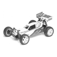
| Vehicle Type | Truck |
| Chassis Type | Tub |
| Shock Type | Oil-Filled |
| Body Type | Truck |
| Terrain | Off-Road |
| Length | 381mm (15 in) |
| Width | 254mm (10 in) |
| Height | 127mm (5 in) |
| Wheelbase | 279mm (11 in) |
| Chassis | Molded Composite |
| Motor Type | Brushed |
Provides crucial safety precautions for assembly and use of the R/C truck.
Attaching front bulkhead, stiffener, and hinge pins.
Installing shock tower and mounting bushings.
Attaching shock tower and body mount.
Assembling front axles and spindles.
Installing ball studs and lock nuts on spindle carriers.
Connecting suspension arms, hinge pins, and braces.
Assembling camber link assemblies using turnbuckles.
Attaching camber links to ball studs on suspension components.
Assembling the servo saver components.
Installing mini lock nuts and ball studs for steering linkage.
Assembling tie rods and drag link with turnbuckles.
Connecting the drag link to the steering idler arm.
Installing steering brace, idler arm, and servo saver assembly.
Connecting tie rods to the steering linkage.
Preparing the servo by trimming mounting ears.
Attaching the servo arm to the servo and connecting to radio system.
Preparing and attaching servo mounting posts to the chassis.
Mounting the servo and chassis brace to the chassis.
Connecting the servo saver to the servo arm.
Securing the front chassis stiffener to the chassis brace.
Assembling rear suspension arms, pivot blocks, and shock brackets.
Attaching rear shock tower and bulkhead.
Attaching rear bulkhead to the pivot plate and chassis.
Attaching dog bones to universal yokes.
Installing universal pivot pins in rear axles.
Securing universal pivots to yokes using Team Losi wrench.