-
Cavro® XLP 6000 Modular Syringe Pump Operating Manual, 734237-C, en
List of Figures
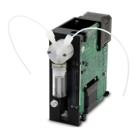
Figure 1-1 XLP 6000 Modular Syringe Pump . . . . . . . . . . . . . . . . . . . . . . . . . . . . 1-3
Figure 1-2 Syringe Components . . . . . . . . . . . . . . . . . . . . . . . . . . . . . . . . . . . . . . 1-4
Figure 1-3 3-Port Valve Components . . . . . . . . . . . . . . . . . . . . . . . . . . . . . . . . . . 1-5
Figure 1-4 XLP 6000 Printed Circuit Assembly External Connectors . . . . . . . . . . 1-6
Figure 2-1 DA-15 Connector Pins . . . . . . . . . . . . . . . . . . . . . . . . . . . . . . . . . . . . . 2-4
Figure 2-2 RS-232 Multi-Pump Cabling. . . . . . . . . . . . . . . . . . . . . . . . . . . . . . . . . 2-6
Figure 2-3 RS-485 Multi-Pump Cabling. . . . . . . . . . . . . . . . . . . . . . . . . . . . . . . . . 2-7
Figure 2-4 CAN Multi-Pump Cabling . . . . . . . . . . . . . . . . . . . . . . . . . . . . . . . . . . . 2-8
Figure 2-5 Address Switch . . . . . . . . . . . . . . . . . . . . . . . . . . . . . . . . . . . . . . . . . . 2-10
Figure 2-6 XLP 6000 Valve Installation (3-Port Valve Shown) . . . . . . . . . . . . . . . 2-12
Figure 2-7 Syringe Installation. . . . . . . . . . . . . . . . . . . . . . . . . . . . . . . . . . . . . . . . 2-13
Figure 2-8 XLP 6000 Outline Drawing. . . . . . . . . . . . . . . . . . . . . . . . . . . . . . . . . . 2-14
Figure 3-1 CAN Message Structure . . . . . . . . . . . . . . . . . . . . . . . . . . . . . . . . . . . 3-11
Figure 3-2 Valve Position Examples for 3-Port Non-Distribution Valves . . . . . . . 3-28
Figure 3-3 Valve Position Examples for 3-Port Distribution Valves. . . . . . . . . . . . 3-29
Figure 3-4 Valve Position Examples for 4-Port Non-Distribution Valves. . . . . . . . 3-30
Figure 3-5 Valve Position Examples for T Valves (Non-Distribution) . . . . . . . . . . 3-31
Figure 3-6 Valve Position Examples for 6-Port Distribution Valves. . . . . . . . . . . . 3-31
Figure 3-7 Valve Position Examples for 9-Port Distribution Valves. . . . . . . . . . . . 3-32
Figure 4-1 Syringe Speed . . . . . . . . . . . . . . . . . . . . . . . . . . . . . . . . . . . . . . . . . . . 4-3
Figure 5-1 Syringe Replacement. . . . . . . . . . . . . . . . . . . . . . . . . . . . . . . . . . . . . . 5-5
Figure 5-2 Syringe Seal Assembly . . . . . . . . . . . . . . . . . . . . . . . . . . . . . . . . . . . . 5-6
Figure 5-3 XLP 6000 Valve Replacement (3-Port Valve Shown) . . . . . . . . . . . . . 5-7
Figure 6-1 XLP 6000 Label Location. . . . . . . . . . . . . . . . . . . . . . . . . . . . . . . . . . . 6-2


 To Next Page