August 2, 2017
SERVICE NOTES for GED-2112
For Qualified Technicians Only
WARNING: No user-serviceable parts inside. Opening and altering the contents within will void the
warranty unless performed by a qualified service technician.
NOTE: The following service notes are recommended as one-time only procedures. It is NOT
recommended to make these changes on a repeated basis.
DESCRIPTION:
The GED-2112 contains two internal jumpers. The first allows the outputs to be tied together so both
channels can be fed through a single output. The second is to configure the operation of the Function
Switch from “mute” to “bypass”.
1. Remove AC cable from unit.
2. Remove bottom cover for access to circuit boards. Carefully unscrew six philips head screws
securing bottom cover to chassis. Be sure to use #2 size screwdriver. Set cover and screws to
the side.
3. Jumpers are located near the FX loop return jack.
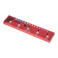
TIE JUMPER: The GED-2112 is shipped from the factory with Drive and Deep channels routed through
their respective XLR and ¼” jacks. This configuration is shown in PHOTO 1 below.
PHOTO 1