Do you have a question about the TechNexion TAM-3517 and is the answer not in the manual?
General guidelines for maintaining the device's condition and longevity.
Information on product compliance and disposal regulations for the European Union.
Overview of the TAM-3517 System on Module (SOM) and its baseboard concept.
Step-by-step guide for initial setup and connection of the TAM-3517W module with a 7" LCD.
Instructions for connecting the TAM-3517W module with a 4.3" LCD baseboard.
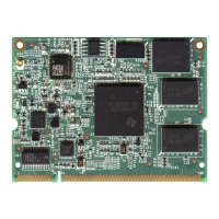
Detailed identification and explanation of components on the TAM-3517W System on Module.
Identification and explanation of components on the Twister Baseboard.
Provides the physical dimensions of the TAM-3517 System on Module.
Provides the physical dimensions of the Twister Baseboard.
Instructions on how to physically install a 2.5" hard disk drive onto the Twister baseboard.
Information on where to find and download necessary drivers and software from the TechNexion website.
Guide to installing the Android OS on the board using a Linux environment.
Guide to installing the Android OS on the board using a Windows environment.
Instructions on how to boot the system directly from an SD card.
Steps for installing applications on the board within the Android environment.
Method for installing Android applications using a network connection.
Guide to installing the Angstrom Linux OS on the board using a Linux environment.
Guide to installing the Angstrom Linux OS on the board using a Windows environment.
Instructions on how to boot the system directly from an SD card using Angstrom Linux.
Details of the TechNexion Board Support Package (BSP) contents for the TAM3517.
Procedures related to system compilation and SD card deployment.
Important warnings regarding the installation of Windows CE, including warranty voiding.
Guide on connecting a null-modem cable for serial communication during installation.
Instructions for updating to Windows Embedded CE6.0 R3, including patch information.
Procedures for downloading and installing the Board Support Package (BSP) for Windows CE.
Step-by-step guide for creating a bootable SD card for Windows CE.
Instructions for writing the Windows CE image to the device's NAND flash memory.
Guide on customizing the boot-up logo for the Windows CE environment.
Technical drawing and dimensions for the nut used to fix the TAM-3517 module.
A block diagram illustrating the internal architecture and components of the TAM-3517W.
Circuit schematics for the Twister baseboard, detailing component connections and layout.
Pinout details for the main module connector, specifying pin assignments.
Pinout and configuration details for the SPI1 interface.
Pinout and switch configuration for UART1 and UART3 interfaces.
Pinout details for the VGA connector pin header.
Pinout details for the LVDS connector, including data and power pins.
Pinout and switch configuration for RS-422/485 serial communication.
Configuration options for GPIO switches (SW3) related to display and system settings.
Describes the procedure for automatic system updates via the NAND Flash.
Configuration options for the USB client/host switch (SW4).
Pinout details for CANBUS interfaces (CAN1 and CAN2).
Details of the RS-232 cable accessory, including pin connections.
Locations for JTAG (Joint Test Action Group) solder points on the board.
| CPU Speed | 600 MHz |
|---|---|
| RAM | 256 MB DDR2 |
| Power Supply | 5V DC |
| Operating Temperature | -20°C to +70°C |
| Connectivity | Ethernet, USB, Serial |
| Processor | TI AM3517 ARM Cortex-A8 |
| Operating System | Linux |
| Ethernet | 10/100 Mbps |
| USB Ports | 2 x USB 2.0 Host |
| Display | LCD interface |