120
5.3.3 A1 BOARD CHECKING
Power supply:
-main power supply 230Vac on terminals “N/U” (block CN1)
-red LED “T” lighted
A1 board generates 2 control power supplies:
• one regulated 5Vdc (+/- 0.5V)
• one non regulated 10 / 16 Vdc – can be checked on terminals “H1/H3” (block CN5)
Communication line:
-terminals +/- (block CN4) : 10Vdc <U< 16Vdc
-green LED “C” lighted (glittering when communication)
Sensors:
-sensor inputs voltage with sensors disconnected (block CN8): 4.5<U<5.5Vdc
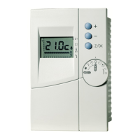
-temperature values displayed on system remote ctrl box
-resistance value of sensors: NTC 10kΩ at 25°C – see table § 5.5
Inputs:
-electric heater default (terminals “A3/C” of block CN6):
If disconnect = alarm “HE” displayed on system remote ctrl box and voltage on terminals = 10 / 16 Vdc
-load shedding contact (terminals “D1/D2” on block CN4):
if contact open or not connected, voltage on terminals = 5Vdc
-load shedding signal (terminals “T+ / T-“ on CN3):
Not connected: red LED “T” flashing
Connected in normal condition: red LED “T” lighted permanently
Outputs:
-forcing outputs (electric heater outputs by means of special parameter (P40) on system remote control box
-when electric heater activated, green LED “A” is lighted
Configuration:
-A1 board code (indicated on identification label):
for heat pumps in version “A” = code 2220126 + board revision
for heat pumps in version “B” = code 2220171 + board revision
-Software version: see parameters P81with system remote control box; check also version of the other
boards (P80 / P85) and especially System remte control box (P80).
Refer to the specific System Service Manual 1012212.
 Loading...