13
EN
1
FACTORY STATE
1=OFF 2=OFF 3= OFF 4=OFF
5=ON 6=ON
JP2=CLOSE JP3=CLOSE
2
1=ON 2=OFF 3=OFF 4=OFF
5=ON 6=ON
JP2=OPEN JP3=CLOSE
3
1=OFF 2=ON 3=OFF 4=OFF
5=ON 6=ON
JP2=CLOSE JP3=OPEN
4
1=ON 2=ON 3=OFF 4=OFF
5=ON 6=ON
JP2=OPEN JP3=OPEN
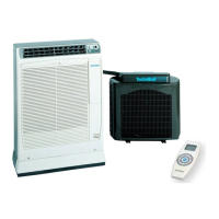
REMOTE CONTROL UNIT
PCB
UNIT
Set JP2 and JP3 as shown in the table.
Proceed as follows:
• Disconnect the power of the unit.
• Remove the batteries from the remote control unit.
• Set the microswitches (see table).
• Insert the batteries in the remote control unit.
• Switch on the unit.
At this point the unit starts operating with the new address.
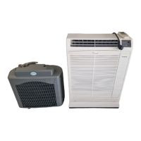
MATCH BETWEEN REMOTE CONTROLLER AND THE UNIT
The remote control can be addressed for 4 different units installed in open space or similar:
-you can get unified control with only one remote control up to 4 units
or
-each remote control is addressed to its unit, so that it can control separately the temperature, the timer and all the
other functions.
 Loading...