3
Adjusting the Saddle Height
To adjust the saddle and seat posi-
tion correctly and safely, please refer
to the information in the original op-
erating instructions which can be found in the
chapter “Adjusting the bicycle to the rider”.
The seat post has been folded for transport.
Open the quick release or loosen the Allen key
on the seat post clamp and pull the seat post
into the suitable position.
Please note that the saddles of Pedelecs that
are equipped with a hydraulic or spring-operated
seat post may sink a little after you have mounted
them. This changes the seat position.
Once you have found a suitable seat position,
close the quick release again or tighten the
screw of the seat post clamp again.
The seat post has a minimum lowering depth that
can be found at the bottom end of the seat post. If
it is exceeded, there is risk of breakage.
Assembly
After assembly and adjustments are
complete, be sure to check that all
screw connections and fas-
teners are securely xed.
The vehicle has had lubricants applied at various
locations. Always wear appropriate clothing and
personal protective equipment, such as suitable
gloves, when assembling.
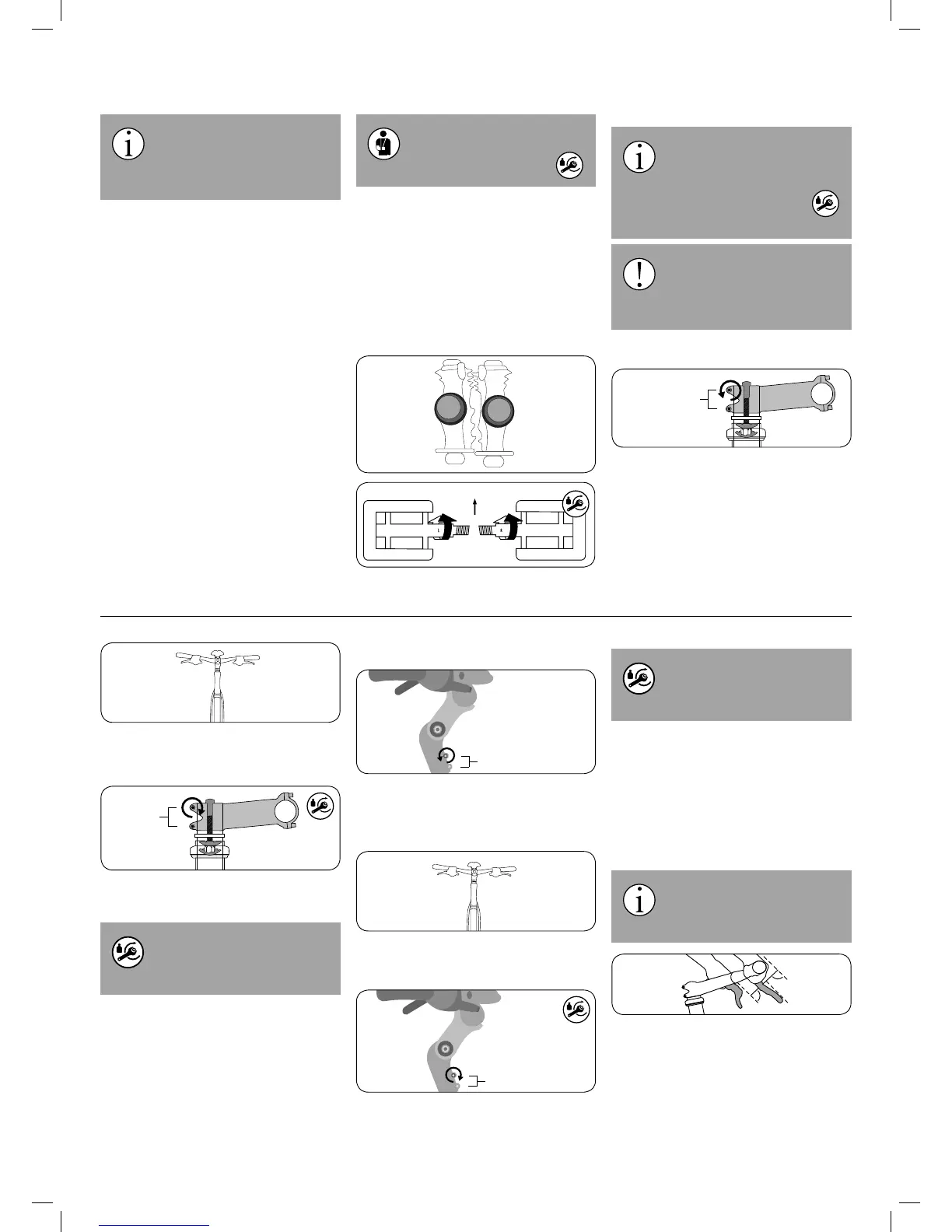
Assembling the Pedals
The pedals are marked “L” for “left” and “R” for
“right”. Turn the right pedal into the crank arm on
the chainring side and the left pedal on the op-
posite side.
Apply assembly grease to both threads before
installing the pedals.
Note that the right pedal must be
turned clockwise, while the left ped-
al must be turned counterclockwise.
To do this, use an open-end wrench, an Al-
len key or a special long pedal
wrench. The appropriate tightening
torque is 40 Nm.
If the pedals are mixed up or cross-
threaded, the threads will be dam-
aged. The pedals could break o
from the crank, which can lead to a crash
and severe injuries.
A-Head Stem
1. Loosen the stem clamping screw of the stem
with a 5 mm hex key, turning counter-clock-
wise. Back it out only a few turns.
2. Align the stem so that the handlebars are at
exactly a 90 degree angle, perpendicular to
the front wheel.
3. Now use a torque wrench to tighten the stem
clamping screws clockwise.
An A-head stem must be tightened
to 6 – 8 Nm. If a dierent tightening
torque is marked on the component,
use that torque instead.
Adjustable A-Head Stem
1. Loosen the stem clamping screw on the bot-
tom of the stem with a 5 mm hex key, turn-
ing counter-clockwise. Back it out only a few
turns.
2. Align the stem so that the handlebars are at
exactly a 90 degree angle, perpendicular to
the front wheel.
3. Now use a torque wrench to tighten the stem
clamping screws clockwise.
An A-head stem must be tightened
to 10 – 12 Nm. If a dierent tighten-
ing torque is marked on the compo-
nent, use that torque instead.
Information on adjusting an adjustable stem can
be found in the chapter “Adjusting the bicycle to
the rider” and possibly also in the enclosed in-
structions of the parts manufacturer.
Brake Levers
Set up your brake levers in such a way that you
can safely apply them and brake comfortably.
The brake levers should be set up
so that your hands can apply them
as a straight extension of your
arms.
 Loading...