o The functionality of the LED is described in section TBD
The front panel shall have an IR receiver
There are no buttons on the front panel
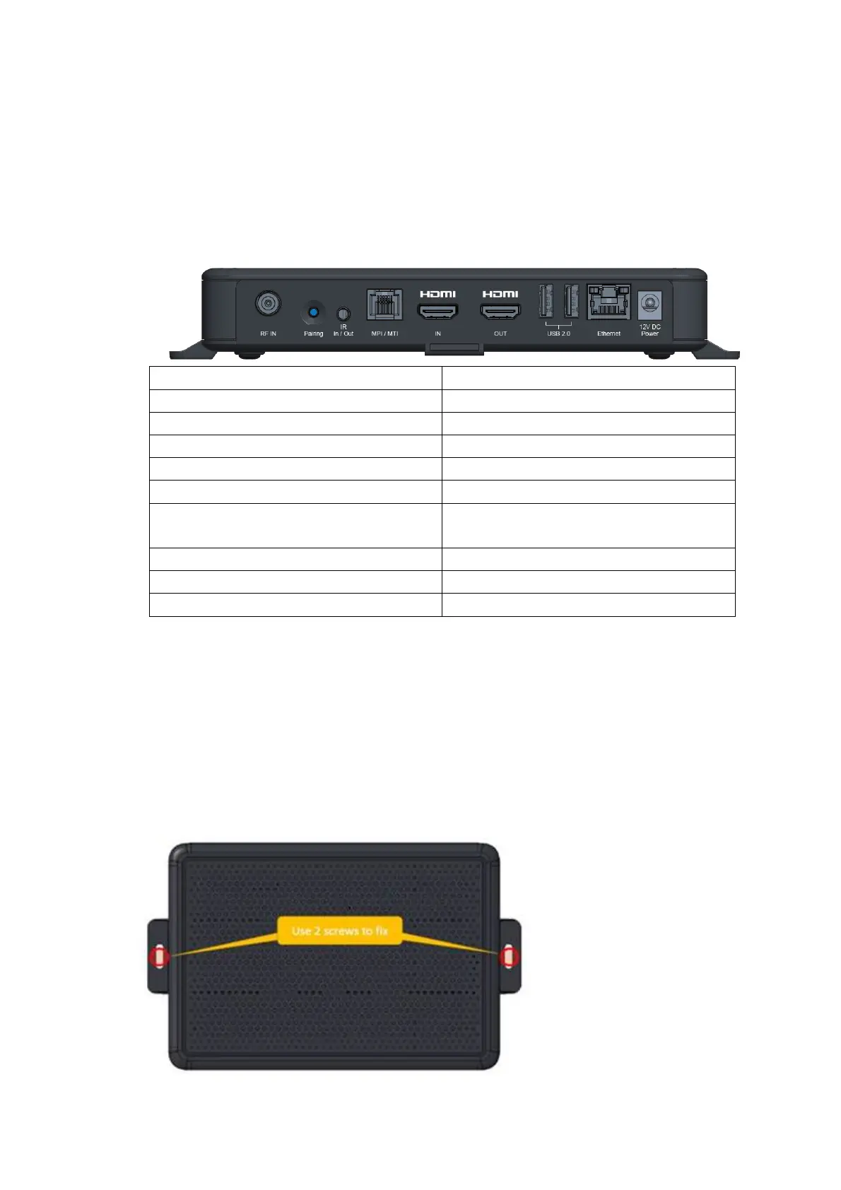
Rear Panel description
The rear panel shall have the following connectors and buttons. The associated label is shown next to the
feature.
Description Label
One Network in F connector Cable Network
2 x USB2.0 Port Type “A” Connector USB
HDMI Connector Type A, for output HDMI IN
HDMI Connector Type A for input HDMI OUT
DC Power Inlet Connector POWER IN
Ethernet RJ45 connector with single LED to indicate
network connectivity
ETHERNET
Pairing button BT Pairing/Wifi Pairing
RJ12 connector for the MPI/MTI interface MPI/MTI
RCA stereo jack for the IR Blaster/IR Receiver Remote IR
Wall Mount Concept
The housing will have tabs on the side to allow for mounting to wall.
Tips of wall mount installation:
1. Place all the items from the packaging on a work table
2. Put STB on the wall in portrait orientation with the front panel facing up and bottom side against to wall
3. Use 2 M4 screws (not included in the STB packaging) to mount the STB on wall through 2 VESA tabs on
left/righ side