Do you have a question about the Technics SA-EH600 and is the answer not in the manual?
| Brand | Technics |
|---|---|
| Model | SA-EH600 |
| Category | Stereo System |
| Language | English |
Details power output, harmonic distortion, and input sensitivity of the amplifier.
Covers FM/AM tuner ranges, sensitivity, and timer functions.
Provides power supply, consumption, dimensions, and weight.
Explains the unit's protection circuit and how it operates.
Lists included accessories like power cord, batteries, and remote.
Safety warnings and instructions for the AC power cord and fuse replacement.
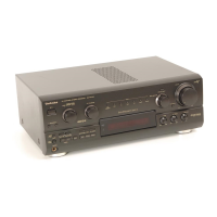
Identifies and explains the function of each control on the unit.
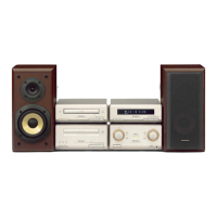
Guides on component setup and optimal speaker positioning.
Instructions for connecting system components, cables, and antennas.
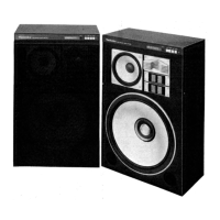
Steps for connecting speaker wires and warnings on impedance.
Details on connecting external sources and optional antenna installation.
How to use RDS for station info and display program types (PTY).
Step-by-step guide to set the 24-hour clock on the unit.
Guides on immersive sound modes and center speaker adjustment.
Using test signals to balance speaker output levels for surround sound.
Instructions for selecting external sources and playing them.
Procedures for checking tuner, Dolby Pro Logic, and power supply PCBs.
Guidance on replacing major components like power ICs and transistors.
Steps to check operation and main printed circuit boards.
Detailed steps for disassembling and removing the main P.C.B.
Steps to replace power IC and regulator transistors with precautions.
Methods for testing unit power and signal output.
How the unit displays error codes and procedures to correct them.
List of schematic diagram sections and important safety/technical notes.
Detailed schematic of the tuner circuit, including signal flow.
Schematic of the FM/AM IF AMP and related components.
Schematic detailing the main IC and its connections for operation.
Schematic of interface ICs and control signals for various functions.
Schematic for RDS signal demodulation IC and related circuits.
Schematic of the main IC for Dolby Pro Logic processing and control.
Schematic of the electronic volume IC and associated filter circuits.
Schematic for muting and attenuation control transistors.
Schematic of PHONO and EXT input terminals and their associated circuits.
Block diagram showing interconnections between main, tuner, and Dolby circuits.
Schematic for the digital sound controller IC and graphic equalizer.
Schematic for motor drive, attenuator, and headphone amp circuits.
Schematic of power supply control, regulators, and drivers.
Schematic of the power supply circuit, including regulators and switches.
Diagram showing connections to speaker terminals for different speakers.
Schematics for the power transformer circuits (A) and (B).