Do you have a question about the Technics SA-EX140 and is the answer not in the manual?
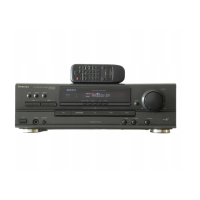
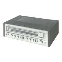
Identifies and explains the buttons and controls on the main unit.
Describes the functions of the remote control buttons and operation.
Procedures for checking the operation of major printed circuit boards.
Step-by-step guides for replacing key components like ICs and motors.
Lists necessary equipment and connection setup for troubleshooting.
Step-by-step test procedures for the amplifier circuit.
Identifies normal waveforms and likely faulty circuit blocks.
Visual representations and types of integrated circuits, transistors, and diodes.
Detailed explanation of pin functions for key integrated circuits.
High-level overview of the unit's internal circuit blocks and signal flow.
Detailed electrical schematic for the tuner section.
Second schematic diagram, likely related to tuner or IF amplification.
Detailed electrical schematic for the panel control circuits.
Detailed electrical schematic for the volume control circuit.
Schematic diagram for the headphone jack circuit board.
Detailed electrical schematic for the main printed circuit board.
Detailed electrical schematic for the transformer circuit board.
Detailed electrical schematic for the power supply circuit board.
Continuation of the power supply circuit schematic.
Diagram showing how internal PCBs and components are interconnected.
Visual guide to the location of cabinet parts with reference numbers.
Comprehensive list of electrical components, part numbers, and descriptions.
Lists packing materials and included accessories with their part numbers.
| Tuning Range | FM, MW |
|---|---|
| Input Sensitivity | 150 mV |
| Signal to Noise Ratio | 80dB (line) |
| Dimensions | 430 x 125 x 300mm |
| Speaker Load Impedance | 8Ω to 16Ω |