EasyManuals Logo

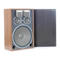
Technics SB-G400 User Manual

Technics SB-G400
4 pages
To Next Page IconTo Next Page
To Previous Page IconTo Previous Page
Page #2 background imageLoading...
Page #2 background image
SB-G400/K,
SB-G500/K:
-SB-G500
sch
ic
di
be
modified
at
=
SCHEMATIC
DIAGRAM
{Te
seremeneaetscy
@
CIRCUIT
BOARD
TO
SPEAKER
TERMINAL
To
SPEAKER
TERMINALED
Ve
Praag
ter
Pe
Tae
ae
ah
.
&
re
2
Late
Nears
TO
TWE
>
TO
TWEETE
>
¥O
SUPER
TWEETE
>
VO
SUPER
TWEETES
>
TO
SUPER
TWEETE
TO
SUPER
TWEETE
~TO
MIDRANGEO
|
.
-.
Pe
igs
ot
a
:
ee:
'
a
Le
a
Cle
:
t
eh
Ep
.
.
.
oe
Aine
.
;
.
i
EE,
tet
ee
RY,
40
0e
EE
-
OP
eee.
+
ee
“om,
:
.
a x
Sere
i
.
cae
See
:
F
ees
ae
rae
dic
.
2+
:
?
/
sediinomtiiies
OF
YOUR
SPEAKER
SYSTEM
The
sound
reproduced
by
@
speaker
system
Ie
eatily
(tr
.
Sluenced
by
such
factors
as
s9Om
acoustics
and
the
place
where
it
is
placed
in
the
room.
Before
finally
deciding
upon
“near
@
Corner
of
near
@
wall,
the
level
of
the
bass
sound
|
_
willl
be
increased
by
the
seflectlons
of
the
sounds
from
a
the
place
where
the
speaker
systems
are
to
be
placed,
please
carefully
read
the
following
information.
®
In
general,
if
a
speaker
system
Is
placed
on
the
floor,
'
"+.
the
wall
and
floor.
Consequently,
it
is
possible
to
adjust
B
oi
a
'
the
bass
sound
to
some
extent
by
changing
the
distance
.
between
the
speaker
systems
and
the
wall
and/or
floor.
Determine
the
location
of
the
speaker
systems
which
-
gives
the
best
sound
reproduction,
therefore,
depending
~
upon
the
actual
conditions
of
the
room
in
which
they
are
to
ba
used.
oe
;
@
If
the
speaker
system
faces
toward
@
hard
wall
or
a
glass
8
heed
meas
the
record
player,
and
should
never
be
-
-
placed
on
the
same
table
or
shelf
as
the
record
player.
it
-
onal
oar
.
om:
amma
cee
ae
ae
-
came
.
?
its
7
CONNECTING
THE
SPEAKER
SYSTEM
and
the
pecors
pleyer.
is
¢
door
or
window,
it
|s
recommended
that
curtains
or
‘shmiter
materiel
be
used
in
order
to
prevent
undesirable
vesonance
and
sound
reflection,
especially
of
the
treble
|
sound.
Vibrations
from
the
speaker
systems
may
be
transmitted
to
a
record
player,
causing
acoustic
feedback
(“howling”).
For
best
results,
the
speaker
systems
should
not
be
is
often
very
effective,
in
order
to
prevent
“howling”,
to
.,
Place
a
thick
plece
of
felt
beneath
se
speaker
systems
“¢
Be
sure
to
tum
off
the
power
of
the
amplifier
mae
.
Connecting
the
speaker
systems
to
It.
SB-G400
|
SB-G500
¢
thick
wire
ts
used,
make
the
connecilon
a
ieee
in
figure
tb.
\
0.
Serige
wtraeut
Zar
(8°
9
Gl
the
tMisutations
frase
she
wire,
and
then
twist
the
core.
2.
Remove
the
terminal
knob
by
turning
it
counterclock-
wise,
insert
the
core
wire
through
one
of
the
notches
on
the
terminal
base,
pass
it
clockwise
around
the
screw,
_
and
out
from
the
other
notch.
3.
Put
the
terminal
knob
back
on
the
screw,
and
tighten
it
“by
turning
it
Sone
Be
sure
that
the
core
}
wires
don’t
touch
each
other.
a
POWER-
HANDLING
CAPACITY
The
power-handling
capacity
of
this
unit
Is
Indicated
In
the
specifications,
and
is
determined
according
to
the
tempare-
ture
increase
of
the
voice
coils.
tf
the
amplifier
to
be
used
has
an
output
power
which
exceeds
the
power-handling
capacity
of
this
unit,
be
sure
that
the
amplifier’s
volume
control
is
set
so
that
exces-
sive
input
Is
not
applied
to
the
speaker
system.
Even
if
the
amplifier
to
be
used
has
an
output
power
which
is
less
than
the
power-handling
capacity
of
this
unit,
the
output
of
the
amplifier
will
become
distorted
and
excessive
input
will
be
applied
to
the
speaker
units,
especially
for
the
middle
and
high
frequencies,
if
the
The
impedance
of
this
speaker
system
is
8
ohms.
Be
sure
that
the
toad
impedance
of
the
satel
to
be
used
is
4
~
16
ohms.
The
Input
terminats
of
this
unit
are
on
the
sear
+
surface
.
of
the
enclosure.
The
polarity
(+
and
—)
of
each
Input
terminal
is
indicated.
When
connecting
speakers
wires:
.
from
the
amplifier,
be
sure
that
the
left
and
sight
con-
|
nections
and
the
plus
and
minus
connections
are
made
;
.
gorrectly.
When
speaker
connection
wires
are
connected
to
the
|
-
“system
input”
terminals,
make
the
connections
as
shown
|:
in
figure
ta.
AL
Strip
about
10mm(1/2”)
of
the
insulation
from
the
wire,
and
then
twist
the
core,
2.
Loosen
the
terminal
knob
by
turning
it
counterclock-
.
wise
2
or
3
times.
Insert
the
wire
into
the
hole
on
the
knob
until
the
core
cannot
be
seen.
;
3.
Tighten
it
by
turning
it
clockwise.
.
a
'
-
Input
signals
to
the
amplifier
are
too
large
or
the
ampll-
fier
volume
level
is
too
high.
Also
note
that
higher-
than-normal
power
is
applied
to
the
speaker
systems
if
.
the
tone
controls
of
an
amplifier
or
a
frequency
equalizer
are
used
to
raise
the
level
of
bass
and/or
treble
sounds.
When
adjusting
the
volume
level,
therefore,
do
so
with
great
care:
confirming
that
amplifier
output
is
not
dis-
torted.
The
power-handling
capacity
of
this
unit
is
set
for
sepro-
'
duction
of
ordinary
music.
tf
an
oscillator
or
test
record
is
used
to
produce
a
continuous
signal
such
as
a
sine
ce
wave,
etc.,
a
signal
exceading
2
watts
must
never
be
applied.
Usually,
1
watt
of
sine
wave
is
enough
to
test
a
speaker
system
when
an
oscillator
of
test
disc
is
used,
If
the
following
special
types
of
signals
are
applied
to
the
speaker
system,
be
sure
to
reduce
the
volume
level
of
the
amplifier.
1.
interstation
hiss
on
the
FM
broadcast
band.
-
2,
Output
from
a
tape
deck
dusing
fast
forward
or
rewind.
.
Acoustic
feedback
from
@
microphone
or
an
ene
musical
instrument.
-
“Shock”
nolse
which
occuss
when
input
or
output
Connaction
cords
are
connected
or
disconnected
or
when
8
Laeaieg
cortridge
ls
seplaced.
~~
=
-
7
.
¢

Questions and Answers:

Question and Answer IconNeed help?

Do you have a question about the Technics SB-G400 and is the answer not in the manual?

Technics SB-G400 Specifications

General IconGeneral
BrandTechnics
ModelSB-G400
CategoryStereo System
LanguageEnglish

Related product manuals