Do you have a question about the Technics ST-CH770 and is the answer not in the manual?
Advises manual is for experienced technicians; warns against self-service.
Instructions to view error codes like U-70 CD, U-70 DECK, F-61 and exit.
Details common codes, causes, and correction procedures.
Steps for checking tuner, dolby pro logic, operation, and video jack PCBs.
Procedures for accessing and checking the main printed circuit board.
Instructions for powering main and tuner circuits for testing.
How to use an oscilloscope to verify output signals from external terminals.
Lists tools and steps for RDS BPF adjustment.
Provides schematics for tuner circuits across different regions.
Schematics for operation control, main circuit, and Dolby Pro Logic circuits.
Schematic of FM front end, mixer, and PLL frequency synthesizer.
Schematic for microcomputer, power supply, and RDS decoder.
Schematic of FM front end, AM/FM loop filters, mixer, and PLL synthesizer.
Schematic for FM IF amp, decoder, VCO, and control signals.
Schematic for FL display, drive circuits, and system control microcomputer.
Schematic for phono EQ, input selector, and buffer amplifier stages.
Detailed pinout and function description for IC901 Microcomputer.
Pinout and function description for IC552 Microcomputer (E/EG areas).
| Brand | Technics |
|---|---|
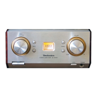
| Model | ST-CH770 |
| Category | Stereo System |
| Language | English |