@
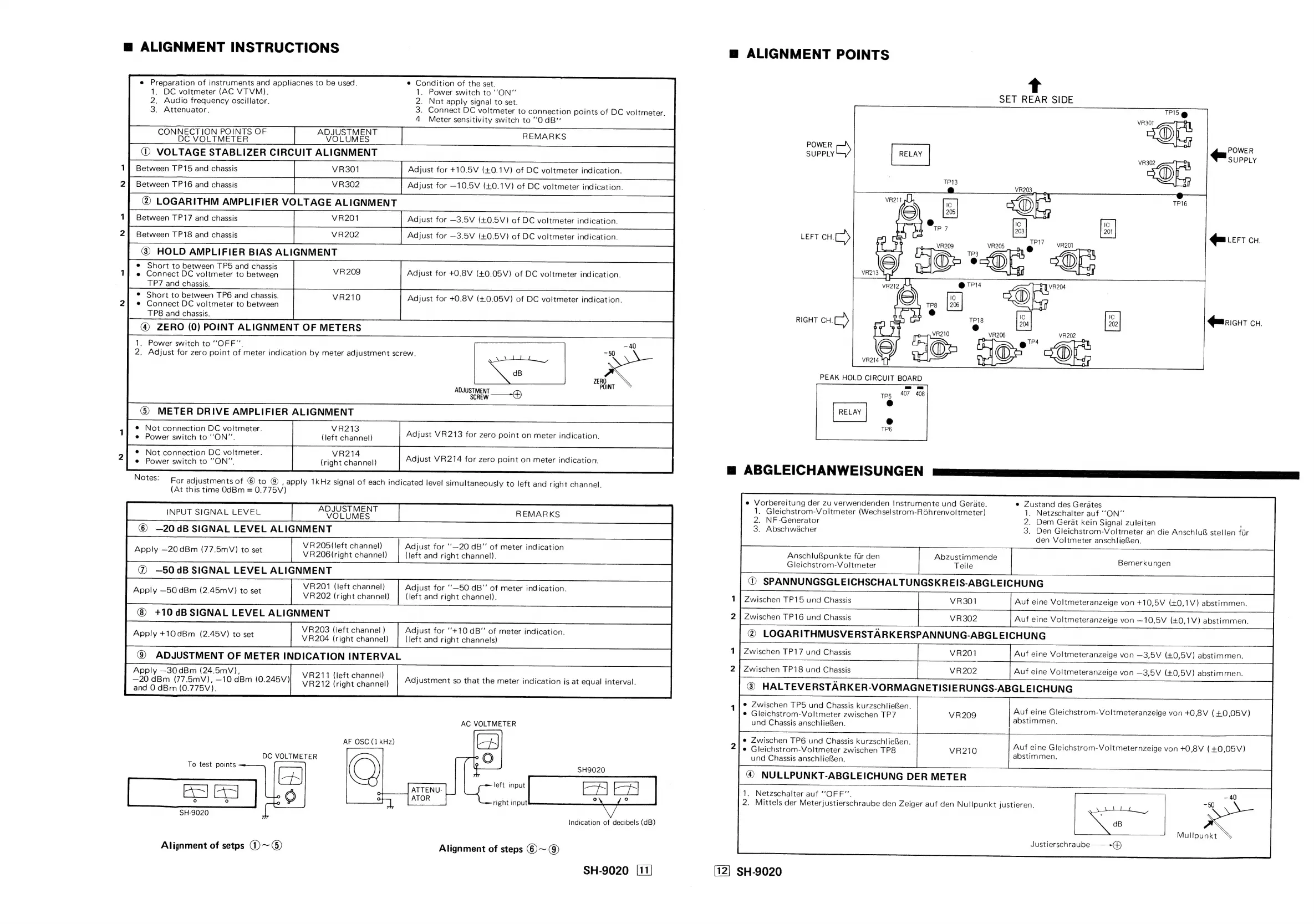
ALIGNMENT
INSTRUCTIONS
e
Preparation
of
instruments
and
appliacnes
to
be
used.
e
Condition
of
the
set.
1.
DC
voltmeter
(AC
VTVM).
1.
Power
switch
to
‘‘ON”
2.
Audio
frequency
oscillator.
2.
Not
apply
signal
to
set.
3.
Attenuator.
3.
Connect
DC
voltmeter
to
connection
points
of
DC
voltmeter.
4
Meter
sensitivity
switch
to
““OdB”
CONNECTION
POINTS
OF
ADJUSTMENT
DC
VOLTMETER
VOLUMES
REMARKS
@)
VOLTAGE
STABLIZER
CIRCUIT
ALIGNMENT
VR301
Adjust
for
+10.5V
(+0.1V)
of
DC
voltmeter
indication.
VR302
Adjust
for
—10.5V
(40.1V)
of
DC
voltmeter
indication.
2)
LOGARITHM
AMPLIFIER
VOLTAGE
ALIGNMENT
VR201
Adjust
for
—3.5V
(+0.5V)
of
DC
voltmeter
indication.
Adjust
for
—3.5V
(+0.5V)
of
DC
voltmeter
indication.
@)
HOLD
AMPLIFIER
BIAS
ALIGNMENT
P5
and
chassi
;
et ee
:
ee
De
vomneie
‘6
baiwecn
VR209
Adjust
for
+0.8V
(40.05V)
of
DC
voltmeter
indication.
_
TP7
and
chassis.
°
Short
to
between
TP6
and
chassis.
VR210
Adjust
for
+0.8V
(40.05V)
of
DC
voltmeter
indication.
e
Connect
DC
voltmeter
to
between
TP8
and
chassis.
@)
ZERO
(0)
POINT
ALIGNMENT
OF
METERS
1.
Power
switch
to
“OFF”.
2.
Adjust
for
zero
point
of
meter
indication
by
meter
adjustment
screw.
Between
TP15
and
chassis
24
Between
TP16
and
chassis
Between
TP17
and
chassis
21
Between
TP18
and
chassis
ADJUSTMENT
a
SCREW
©
METER
DRIVE
AMPLIFIER
ALIGNMENT
ner
eel
Adjust
VR213
for
zero
point
on
meter
indication.
p
SOR
COO
me
OO
Me
etel
vie
ls
Adjust
VR214
for
zero
point
on
meter
indication.
e
Power
switch
to
“ON”,
(right
channel)
e
Not
connection
DC
voltmeter.
e
Power
switch
to
‘ON”’.
Notes:
Fo,
adjustments
of
©
to
@
,
apply
1kHz
signal
of
each
indicated
level
simultaneously
to
left
and
right
channel.
(At
this
time
OdBm
=
0.775V)
©
-—20dB
SIGNAL
LEVEL
ALIGNMENT
VR205
(left
channel)
Adjust
for
‘‘—20
dB"
of
meter
indication
VR206(right
channel)
(left
and
right
channel).
@
—50dB
SIGNAL
LEVEL
ALIGNMENT
VR201
(left
channel)
Adjust
for
‘‘—50
dB”’
of
meter
indication.
VR202
(right
channel)
(left
and
right
channel).
+10
dB
SIGNAL
LEVEL
ALIGNMENT
VR203
(left
channel!
)
Adjust
for
‘+10
dB”
of
meter
indication.
VR204
(right
channel)
(left
and
right
channels)
@
ADJUSTMENT
OF
METER
INDICATION
INTERVAL
Apply
—30
dBm
(24.5mV),
—20
dBm
(77.5mV),
—10
dBm
(0.245V)
and
0
dBm
(0.775V).
Apply
—20
dBm
(77.5mV)
to
set
Apply
—50
dBm
(2.45mV)
to
set
Apply
+10dBm
(2.45V)
to
set
VR211
(left
channel)
VR212
(right
channel)
Adjustment
so
that
the
meter
indication
is
at
equal
interval.
AC
VOLTMETER
AF
OSC
(1
kHz)
DC
VOLTMETER
To
test
points
CF
|
ES
|
bo
SH-9020
SH9020
left
|
t
ATTENU-
ee
Peeled
ATOR
right
input
2
=
Indication
of
decibels
(dB)
Alignment
of
setps
@)~
©)
Alignment
of
steps
©)
~
@)
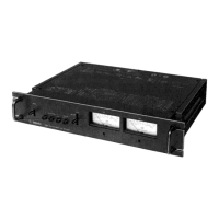
SH-9020
[11]
@
ALIGNMENT
POINTS
SET
REAR
SIDE
TPIS
VR301
a1
VR302
rt
|
POWER
SUPPLY
POWER
C)
SUPPLY
qmicrr
CH.
Qmnicht
cu.
m@
ABGLEICHANWEISUNGEN
e
Vorbereitung
der
zu
verwendenden
Instrumente
und
Gerate.
e
Zustand
des
Gerates
1.
Gleichstrom-Voltmeter
(Wechselstrom-Rohrenvoltmeter)
1.
Netzschalter
auf
‘‘ON”’
2.
NF-Generator
2.
Dem
Gerat
kein
Signal
zuleiten
3.
Abschwacher
3.
Den
Gleichstrom-Voltmeter
an
die
Anschlu
stellen
fir
den
Voltmeter
anschlieen.
Anschluf&punkte
flr
den
Abzustimmende
Gleichstrom-Voltmeter
Teile
©
SPANNUNGSGLEICHSCHALTUNGSKREIS-ABGLEICHUNG
Zwischen
1TP15
und
Chassis
VR301
Bemerkungen
Auf
eine
Voltmeteranzeige
von
+10,5V
(40,1V)
abstimmen.
2
|
Zwischen
TP16
und
Chassis
VR302
@)
LOGARITHMUSVERSTARKERSPANNUNG-ABGLEICHUNG
Zwischen
TP17
und
Chassis
VR201
Auf
eine
Voltmeteranzeige
von
—10,5V
(£0,1V)
abstimmen.
1
Auf
eine
Voltmeteranzeige
von
—3,5V
(+0,5V)
abstimmen.
2
|
Zwischen
TP18
und
Chassis
VR202
Auf
eine
Voltmeteranzeige
von
—3,5V
(+0,5V)
abstimmen.
@
HALTEVERSTARKER-VORMAGNETISIERUNGS-ABGLEICHUNG
e
Zwischen
TP5
und
Chassis
kurzschlieRen.
e
Gleichstrom-Voltmeter
zwischen
TP7
und
Chassis
anschliefen.
Auf
eine
Gleichstrom-Voltmeteranzeige
von
+0,8V
(+0,05V)
abstimmen.
e
Zwischen
TP6
und
Chassis
kurzschlieen.
e
Gleichstrom-Voltmeter
zwischen
TP8
und
Chassis
anschlieken.
@
NULLPUNKT-ABGLEICHUNG
DER
METER
1.
Netzschalter
auf
“OFF”.
2.
Mittels
der
Meterjustierschraube
den
Zeiger
auf
den
Nullpunkt
justieren.
Auf
eine
Gleichstrom-Voltmeternzeige
von
+0,8V
(+0,05V)
abstimmen.
—
40
-50
dB
Mullpunkt
©
Justierschraube
SH-9020
 Loading...