EasyManua.ls Logo

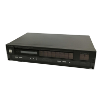
Technics ST-G3

Technics ST-G3
21 pages
To Next Page IconTo Next Page
To Previous Page IconTo Previous Page
Loading...
|
ST-G3_ST-G3
|
FM
SIGNAL
GENERATOR
CONDITION
Modulation
30%
Modulation
frequency..
Output
level
@
MEASUREMENTS
AND
ADJUSTMENTS
=
AM/FM
SIGNAL
STRENGTH
LEVEL
ADJUSTMENT
.
Test
equipment
connection
is
shown
in
figure.
.
Set
the
unit
to
FM”
position.
.
Place
the
radio
frequency
display
and
signal
generator
setting
to
100,10
MHz.
.
Change
LCD
display
from
frequency
to
dB
by
pressing
the
FM
signal
button.
Control
positions
and
equipment
used
@
AMand
FM
signal
generator
(AM
and
FM-SG).
@
Frequency
counter
@
Stereo
modulator
@
Choke
coil
(100MH)
Distortion
analyser
@
Resistor
(100k{2)
e
®
Oscilloscope
Ceramic
capacitor
(200pF)
e
AC
and
DC
electronic
voltmeter
(EVM)
So,
do
not
turn
the
cores
of
these
parts.
AM-RF
ADJUSTMENT
.
Test
equipment
connection
is
shown
in
figure.
.
Set
the
unit
to
“AM”
position.
Note:
For
7201
(AM-IFT)
and
L203
(AM
OSC
coil),
adjusted
parts
are
supplied.
AM
SIGNAL
GENERATOR
CONDITION
Modulation
30%
.
Adjust
VR101
so
that
54
dB
in
indicated.
.
Make
sure
that
the
signal
strength
level
is
22
~
38
dB
when
the
input
is
30
dB.
Adjustment
points
.
Place
the
radio
frequency
display
and
signal
generator
Modulation
frequency
400
Hz
AC
EVM
Oscilloscope
setting
to
612
kHz.
AM—SG
UNIT
.
Adjust
L202
for
maximum
output.
BS
[ewe
.
Place
the
radio
frequency
display
and
signal
generator
coe
00%
FM
det.
coil
RO
oer
NDAs!
phe
ere
(100.10
MHz)
MENT
MENT
(612
kHz)
(1503
kHz)
setting
to
1503
kHz.
.
Adjust
CT201
for
maximum
output.
.
Repeat
steps
3
~
6.
Note:
Antenna
input
level
must
be
as
low
as
possible
being
free
from
AGC.
FM
MONO
DISTORTION
ADJUSTMENT
.
Test
equipment
connection
is
shown
in
figure.
.
Set
the
unit
to
‘’FM”
position.
.
Place
the
radio
frequency
display
and
signal
generator
setting
to
100.10
MHz.
.
Adjust
T101
core
so
that
voltage
measured
in
signal
mode
is
0
mV
(0
+
50
mV)
in
300
mV
range.
.
Set
the
output
mode
of
stereo
modulation
to
“‘L”
or
‘‘R”
.
Adjust
T102
so
that
“L’
channel
("R”
channel)
is
minimized.
.
Repeat
steps
4
~
6,
and
make
sure
that
the
distortion
is
nearly
same
between
’’L”
and
‘’R’”’
channels
and
is
less
than
4%.
SEPARATION
ADJUSTMENT
.
Test
equipment
connection
is
shown
in
figure.
.
Set
the
unit
to
‘‘FM”
position.
.
Place
the
radio
frequency
display
and
signal
generator
setting
to
100.10
MHz.
.
Adjust
VWR301
so
that
R
output
is
minimized
when
stereo
modulator
is
in
‘’L’’
(L
ch
modulation)
mode.
.
The
mode
must
be
‘’R” for
‘’R’’
channel;
and
L
—»R,
R
—»L
separation
must
be
40
dB
at
least.
i
Capacitor
Output
200pF
terminal
FM
SIGNAL
GENERATOR
CONDITION
Modulation
«.-.
100%
Modulation
frequency
...
400
Hz
Output
level
DCEVM
ACEVM
Choke
FM-SG
UNIT
coil
STEREO
MODULATOR
Output
mode
FM
SIGNAL
GENERATOR
CONDITION
Modulation
“L”
mode
or
“‘R”
mode
90%,
Pilot
10%
1
KHz,
Pilot
(19
kHz)
L.R_Output
@@
-?
terminal
me
YeKeKe)=:)
LPF
(fc
=
15
kHz
~
19
kHz)
STEREO
MODULATOR
VR30I
VRIOI
Separation
adj.
level
adj.
Signal
strength
FM
detector
coil
(100.10
MHz)

Related product manuals