Do you have a question about the Technics ST-HD50 and is the answer not in the manual?
Details input sensitivity, impedance, output level, frequency response, and S/N.
Covers frequency range, sensitivity, S/N, stereo separation, and antenna terminal.
Specifies frequency range and sensitivity for AM reception.
Explains clock type, programmable timer functions, and sleep timer settings.
Lists approximate dimensions and weight of the unit.
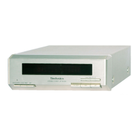
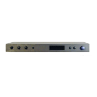
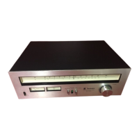
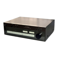
Identifies and describes the function of each button and indicator on the front panel.
Step-by-step guide on how to set the clock and timer functions.
Explains the unit's self-diagnostic function and how it displays malfunction codes.
Details specific display codes (U70 CD, Good-bye) and their corresponding correction procedures.
Procedures for checking circuit boards and replacing main components.
Detailed steps for accessing and inspecting the tuner and FL printed circuit boards.
Instructions for accessing and inspecting the main printed circuit board.
Illustrations and part numbers for ICs, transistors, and diodes used in the unit.
Procedures for supplying power to the unit for testing and servicing.
Guidance on connecting equipment to check output signals.
Overview of the different schematic diagram sections (Tuner, Main, Operation, etc.).
Detailed schematic for the FM/AM tuner section.
Schematic for the input and output signal pathways.
Comprehensive schematic of the unit's main internal circuitry.
Schematic for the front panel display (FL) circuit.
Schematic detailing the operation and control circuits.
Diagram showing component placement on the tuner printed circuit board.
Diagram showing component placement on the connector printed circuit board.
Diagram showing component placement on the input/output printed circuit board.
Diagram showing component placement on the main printed circuit board.
Diagram showing component placement on the FL (display) printed circuit board.
Diagram showing component placement on the operation printed circuit board.
Illustrates how different circuit boards and external components are interconnected.
Detailed pinout and function descriptions for integrated circuits, particularly IC901.
High-level overview of the unit's functional blocks and signal flow.
Comprehensive list of electrical components, their part numbers, and descriptions.
Lists cabinet parts, connectors, switches, relays, and hardware with part numbers.
Detailed listing of resistors and capacitors with their values and part numbers.
List of screws, panels, feet, and holders used in the cabinet assembly.
Diagram showing the location and assembly of cabinet parts.
| Type | Digital Tuner |
|---|---|
| Frequency Range (FM) | 87.5 - 108 MHz |
| Frequency Range (AM) | 522 - 1611 kHz |
| FM Sensitivity | 1.5 µV (IHF) |
| Signal-to-Noise Ratio (AM) | 50 dB |
| Output Level | 500 mV |
| Signal-to-Noise Ratio (FM) | 70 dB |
| Total Harmonic Distortion (FM) | 0.1% |
| Tuning System | Quartz PLL Synthesizer |
| Frequency Response (FM) | 20 Hz - 15 kHz, +0.5/-1.5 dB |