EasyManua.ls Logo

Technics ST-HD350

Technics ST-HD350
24 pages
To Next Page IconTo Next Page
Loading...
Question and Answer IconNeed help?

Do you have a question about the Technics ST-HD350 and is the answer not in the manual?

Technics ST-HD350 Specifications

General IconGeneral
BrandTechnics
ModelST-HD350
CategoryTuner
LanguageEnglish

Summary

Specifications Overview

Pre-amplifier and Tuner Specifications

Input sensitivity, impedance, FM frequency range, and antenna specs.

Timer and General Unit Specifications

Timer functions, dimensions, and mass of the unit.

Critical Safety Warning

Service Preparation and Notes

Handling Service Notes

Refers to separate manual for accessories and packaging information.

System Repair Preparation

Emphasizes connecting the tuner to the amplifier for repair and checking.

Location of Controls

Front Panel Control Identification

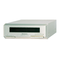
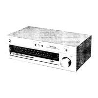
Identifies and describes the function of buttons on the tuner's front panel.

Operation Checks and Component Replacement

FL P.C.B. Checking and Removal

Procedure for checking and removing the FL printed circuit board.

Main P.C.B. Checking and Removal

Procedure for checking and removing the main printed circuit board.

Power Source Connection

Self-Diagnostic Functionality

Displaying Malfunction Codes

Explains how the unit displays malfunction codes like U70 and F61.

Returning to Normal Display

Procedures for clearing malfunction codes and returning to normal operation.

Interpreting Error Code Contents

Describes common error codes like U70 (communication error) and F61 (amplifier output IC fault).

Component Identification

ICs, Transistors, and Diodes Illustrations

Provides illustrations and part numbers for various electronic components.

Schematic Diagram Notes

General Schematic Notes and Safety

Explains modifications, component replacement, and safety precautions.

Voltage and Signal Line Conventions

Defines symbols used to represent voltage and signal lines in diagrams.

Schematic Diagram-1: FL Circuit

Schematic Diagram-2: Operation Circuit

Schematic Diagram-3: Main Circuit

Schematic Diagram-4: Connector Circuit

Schematic Diagram-5: Main Circuit

Schematic Diagram-6: Tuner Unit

Schematic Diagram-7: Tuner Unit

Printed Circuit Board Layouts

FL, Operation, and Connector PCB Layouts

Shows component layouts for FL, Operation, and Connector Printed Circuit Boards.

EXT IN Terminal PCB Layout

Layout of the Printed Circuit Board for the External Input terminals.

Wiring Connection Diagram

System Interconnections Diagram

Illustrates how different PCBs and units connect within the system.

Block Diagram: Tuner Unit

Tuner Unit Functional Blocks

Functional block diagram of the Z101 Tuner Unit, showing signal flow.

Integrated Circuit Terminal Functions

IC601 System ControlFL Drive Pinout

Detailed pinout and function description for IC601.

Replacement Parts List: Mechanical and Electronic Components

Mechanical Parts Listing

Lists screws, cabinets, buttons, and PCB supports with part numbers.

Capacitors, Diodes, and Connectors

Lists capacitors, diodes, connectors, and their specifications.

Replacement Parts List: Components (Continued)

Transistors, ICs, and Coils

Lists transistors, ICs, and coils with part numbers and descriptions.

Resistors Listing

Comprehensive list of resistors with part numbers, types, and values.

Replacement Parts List: Components (Continued)

Resistors Listing (Continued)

Continues the list of resistors with part numbers and values.

Switches, Oscillators, and Sensors

Lists various switches, oscillators, and the remote sensor.

Cabinet Parts Location Diagram

Exploded View of Cabinet Assembly

Illustrates the location and assembly of cabinet parts with reference numbers.

Related product manuals