Do you have a question about the Technics ST-X302L and is the answer not in the manual?
Technical details for FM reception, including sensitivity, selectivity, and frequency response.
Technical details for AM reception, covering frequency ranges, sensitivity, and selectivity for MW and LW.
Information on the unit's timer features, including 24-hour programmability and sleep functions.
Overall electrical and physical specifications like power consumption, dimensions, and weight.
Cables for stereo signal and L-type connections for audio input/output.
Includes FM/AM antennas, remote control, batteries, and AC power cord for operation.
Buttons for setting clock, timer operations, sleep, cancel, and stand-by modes.
Buttons used to check programmed settings and select timer operation types.
Indicators for timer modes (ONCE, WEEKLY, SLEEP), stand-by, and operation status.
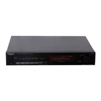
Indicators for time, tuning mode, quartz lock, FM stereo, and channel selection.
Steps for connecting stereo, L-type cables, and flat cables to other audio components.
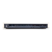
Details on "REMOTE OUT" and "AC OUTLET" terminals for system integration.
Instructions for safely removing the outer cabinet and front panel.
Steps for carefully removing the FL drive and operation circuit boards.
Instructions for removing the main and power supply circuit boards.
Procedure for replacing the unit's rubber feet.
Detailed steps for adjusting FM mono distortion and MPX VCO parameters.
Procedure for adjusting the PLL clock frequency using a frequency counter.
Diagram illustrating the specific locations on the main PCB for various adjustments.
Detailed schematic illustrating the main circuit board layout and components.
Schematics for the operation and sensor/operation circuit boards.
Schematics detailing the power supply circuits for different geographical area configurations.
Wiring diagrams illustrating connections for the main PCB and power supply units.
Wiring diagrams showing connections for operation, sensor, and FL drive circuit boards.
Reference guide for identifying and understanding ICs, transistors, and diodes.
Description of the front panel's FL display elements and their anode connections.
Block diagram of tuner, IF, MPX, and signal processing sections.
Block diagram of microcomputer control, display, and power supply sections.
Detailed functional description for each pin of the main microcomputer IC.
List of ICs and transistors with part numbers and descriptions.
List of diodes, resistors, and capacitors with part numbers and values.
List of switches, antenna/output jacks, and fuses with part numbers.
List of various connectors and variable capacitors with their part numbers.
Detailed list of resistors, including part numbers, values, and wattage.
Detailed list of capacitors, including part numbers and capacitance values.
Continuation of the capacitor list with part numbers and capacitance values.
List of cabinet parts, packing materials, and accessory boxes.
List of accessories like remote control, batteries, and instruction manuals.
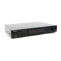
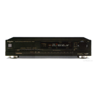
Diagram showing the location of external cabinet parts and connectors.
Illustration showing how the unit and accessories are packed for shipping.
| Tuning Bands | FM, MW, LW |
|---|---|
| FM Tuning Range | 87.5 - 108 MHz |
| MW Tuning Range | 522 - 1611 kHz |
| LW Tuning Range | 153 - 279 kHz |
| Signal to Noise Ratio (MW/LW) | 50 dB |
| Total Harmonic Distortion (MW/LW) | 0.5% |
| Capture Ratio (FM) | 1.5 dB |
| IF Rejection (FM) | 90 dB |
| Output Level | 650 mV |
| Power Consumption | 8 W |
| Tuning System | Quartz Synthesizer |
| FM Sensitivity | 1.2 µV (IHF) |
| Signal to Noise Ratio (FM) | 70 dB |
| Total Harmonic Distortion (FM) | 0.3% |
| Frequency Response (FM) | 30 Hz - 15 kHz |
| Dimensions (W x H x D) | 430 x 76 x 230 mm |
| Power Supply | 220-240V, 50/60Hz |