EasyManuals Logo

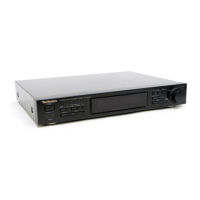
Technics ST-X302L Service Manual

Technics ST-X302L
21 pages
To Next Page IconTo Next Page
To Previous Page IconTo Previous Page
Page #7 background imageLoading...
Page #7 background image
ST-X302L
m@
MEASUREMENTS
AND
ADJUSTMENTS
FM
ADJUSTMENT
Control
positions
and
equipment
used
®FM
signal
generator
(FM-SG)
Frequency
cour
ter
®
Distortion
analyser
Choke
coil
(100
LH)
DC
electronic
voitmeter
(EVM)
Resistor
(100
kQ)
Note:
For
Z251
(AM-ANT/OSC)
and
Z202
(AM-IFT),
they
are
supplied
as
adjusted
parts.
So,
do
not
turn
the
cores
of
the
parts.
It
is
not
necessary
to
adjust
the
AM
circuit.
FM
MONO
DISTORTION
ADJUSTMENT
FM
SIGNAL
GENERATOR
CONDITION
1.
Test
equipment
connection
is
shown
in
figure.
Modulation..............660.
100%
2.
Set
the
unit
to
“FM”
mode.
Modulation
frequency
........
1
kHz
3.
Set
the
radio
frequency
display
and
signal
generator
to
*
Outputlevel
..........00.
66
dB
100.10
MHz.
ere
4.
Adjust
the
core
of
T201
so
that
the
voltage
measured
in
signal
mode
is
0
mV
(0+20
mV)
in
300
mV
range.
5.
Adjust
T202
so
that
the
distortion
factor
of
L-CH
and
R-CHis
minimized.
6.
Repeat
steps
4
and
5.
Note:
The
adjusting
screwdriver
used
should
be
made
of
resin.
ES
fea]
©
feaece
Out
Wooa-----ee
See
MPX
VCO
ADJUSTMENT
1,
Test
equipment
connection
is
shown
in
figure.
EM-SG
prequency
BoUNeE
2.
Set
the
unit
to
‘‘on/auto”
position.
3.
Set
the
radio
frequency
display
and
signal
generator
to
Bird
O
TP301
190
kas
100.10
MHz.
oe
Out
FM
ANT
(750
et
.
(75Q)
|
Chassis
4.
Adjust
VR301
for
19
KHz+30
Hz
on
frequency
counter
reading.
USING
ALTERNATE
SYSTEM
Ss)
1.
Receive
the
stereo
broadcast.
2.
Adjust
VR301
until
stereo
indicator
lights
up.
Fix
the
arm
of
VR301
as
shown
in
figure.
FM
SIGNAL
GENERATOR
CONDITION
“Stereo”
“Stereo”
Modulation.............0.00.
100%
OFF
OFF
Modulation
frequency
........
0
kHz
Outputlevel
.............05.
66
dB
VR301
@®-®,
O-®......
“Stereo”
OFF
position
BHO)
s.
wean
ested
“Stereo”
ON
position
(indicator
lighting)
Oibibesadebiancins
Adjust
point
of
pilot
circuit
PLL
CLOCK
FREQUENCY
ADJUSTMENT
Use
a
high
impedance
probe.
1.
Test
equipment
connection
is
shown
in
figure.
FrOguienicy
countes
2.
Set
the
Power
Switch
to
“OFF”.
(The
indication
“E”
in
the
display
Co)
will
blink.)
3.
Adjust
CT101
for
2,097,152
Hz+10
Hz
on
frequency
counter
reading.
4
7
TP102
(GND)

Questions and Answers:

Question and Answer IconNeed help?

Do you have a question about the Technics ST-X302L and is the answer not in the manual?

Technics ST-X302L Specifications

General IconGeneral
BrandTechnics
ModelST-X302L
CategoryTuner
LanguageEnglish

Related product manuals