Do you have a question about the Technics ST-HD51 and is the answer not in the manual?
Details input sensitivity, output level, and frequency response.
Specifies frequency range, sensitivity, and signal-to-noise ratio.
Lists AM frequency range and sensitivity.
Outlines programmable timer functions and settings.
Provides physical dimensions and weight of the unit.
Instructions for viewing error codes displayed by the unit.
Procedures to reset the unit and resume normal operation.
Steps for inspecting the tuner and fluorescent display circuit boards.
Procedure for inspecting the main printed circuit board.
Method for supplying power to the main circuit during servicing.
Steps to verify signal output from the unit.
Detailed circuit diagram of the tuner section.
Circuit diagram for unit connectors and interfaces.
Circuit diagram illustrating signal input and output paths.
Core circuit diagram detailing the unit's main functions.
Circuit diagram related to the fluorescent display.
Circuit diagram for the unit's operational controls.
Visual layout of the tuner circuit boards for different regions.
Layouts for connector and input/output circuit boards.
Visual layout of the main printed circuit board.
Layouts for fluorescent display and operation circuit boards.
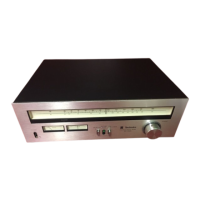
| FM Tuning Range | 87.5 - 108 MHz |
|---|---|
| AM Tuning Range | 530 - 1710 kHz |
| Output | 500 mV |
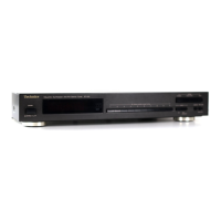
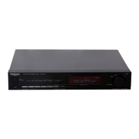
| Type | Tuner |
| Signal-to-Noise Ratio | 50 dB (AM) |
| Total Harmonic Distortion | 0.2% |
| Selectivity | 70 dB |
| Sensitivity | 1.5 µV (FM) |
| Power Supply | 220-240 V, 50/60 Hz |