EasyManua.ls Logo

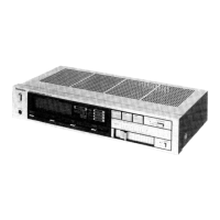
Technics SU-Z35

Technics SU-Z35
20 pages
To Next Page IconTo Next Page
To Previous Page IconTo Previous Page
Loading...
li
LOCATION
OF
CONTROLS
Input
selector
Peak
power
level
meter
Selector
indicators
Power
(Push
on)
ae
Aux/CD/Vi
Tape
monitor
ideo
Ph
TEPEINCIERIOE
ie
(
M@
source,
m=
tape/ext)
Tuner
Headphones
jack
oe.
Teele
Loudness
Speaker
Volume
contro!
(2
oF
=
on)
Tone
controls
Balance
control
Aux/CD/Video
input
[tt
}+-(Unswitched)
ae
outlets
Tuner
input
tt
j
(Switched)
(For
[XA],
[PC]
Phono
input
i
areas
only)
Rec
out
Playback
Voltage
selector
(For
[XA],[PC]
areas
only)
Tape
Speaker
terminal
@
The
power
supply
for
this
unit
varies
depending
upon
the
areas.
Also,
the
parts
used
for
power
supply
are
different.
So,
refer
to
the
circuit
diagram
and
the
replacement
parts
list.
*
[XA,
PC]
areas
is
provided
with
voltage
selector
and
AC
outlets.
*
240V
(50/60Hz)
for
Australia
and
United
Kingdom.
*
220V
(50/60Hz)
for
Continental
Europe.
*
110V/120V/220V/240V
(50/60Hz)
for
other
[XA,
PC]
areas.
*
Phono
input
capacitance
is
about
150pF.
M@
BEFORE
REPAIR
AND
ADJUSTMENT
1.
Turn
off
the
power
supply
and
short-circuit
of
power
supply
capacitors
(C406,
C407,
4700uF)
at
resistance
(about
10Q,
5W)
in
order
to
discharge
the
charged
voltage.
Do
not
short
between
C406/C407
by
screwdriver.
It
may
damage
the
component.
2.
Before
turning
on
the
power
supply
after
completion
of
repair,
slowly
apply
the
primary
voltage
by
using
a
power
supply
voltage
controller
to
make
sure
that
the
consumed
current
is
free
of
abnormality.
The
consumed
current
at
60Hz/50Hz
in
no
signal
mode
is
shown
below
with
respect
to
supply
voltage
110V/120V/220V/240V.
a
a
a
130
~
270
mA
120
~
240
mA
65
~
135
mA
60
~
120
mA
130
~
270
mA
120
~
240
mA
65
~
135
mA
60~
120
mA
Consumed
current

Related product manuals