EasyManua.ls Logo

Technics SU-Z35

Technics SU-Z35
20 pages
To Next Page IconTo Next Page
Loading...
ORDER
NO.
SD83062527C8
Service
Manual
Stereo
Integrated
Amplifier
SU-Z35
[E],
(EGA),
(EK],[EF],
[EH],
[EB},(Ei],[XAl},[XL],[PC]
SU-2Z35(k)
area,
LE!
[EGA],
[EHI,[XA],[PC]
*
[E]
is
available
in
Scandinavia
and
Switzerland.
*
[EGA]
is
available
in
F.R.
Germany.
*
[EK]
is
available
in
United
Kingdom.
*
[EF]
is
available
in
France.
*
[EH]
is
available
in
Holland.
*
[EB]
is
available
in
Belgium.
*
[Ei]
is
available
in
Italy.
*
[XA]
is
available
in
Southeast
Asia,
Oceania,
Africa,
Middle
Near
East
and
Central
South
America.
*
[XL]
is
available
in
Australia.
*
[PC]
is
available
in
European
Audio
Club.
J
*
The
colors
of
this
model
included
silver
and
black.
*
The
black
type
model
is
provided
with
(K)
in
the
Service
Manual.
Specifications
(Specifications
are
subject
to
change
without
notice
for
further
improvement.)
(DIN
45
500)
S/N
rated
power
(40)
@
AMPLIFIER
SECTION
PHONO
72
dB
(IHF,
A:
72
dB)
TUNER,
AUX/CD/VIDEO,
TAPE
86
dB
(IHF,
A:
97
dB)
1
kHz
continuous
power
output
both
channels
driven
2
X
32W
(8Q)
2
x
40W
(40)
~26
dB
power
(40)
40
Hz~20
kHz
continuous
power
output
PHONO
65
dB
both
channels
driven
2
x
30W
(8Q)
TUNER,
AUX/CD/VIDEO,
TAPE
65
dB
2
X
32W
(4)
50
mW
power
(4)
Total
harmonic
distortion
PHONO
62
dB
rated
power
at
1
kHz
0.03%
(82)
TUNER,
AUX/CD/VIDEO,
TAPE
62
dB
0.05%
(40)
Tone
controls
rated
power
at
40
Hz~20
kHz
0.03%
(8Q)
BASS
50
Hz,
+10
dB~
~
10
dB
0.05%
(42)
TREBLE
20
kHz.
+10
dB~
—10
dB
half
power
at
1
kHz
0.005%
(82)
Loudness
control
(volume
at
~
30
dB)
50
Hz,
+9
dB
0.007%
(42)
Output
voltage
and
impedance
half
power
at
40
Hz~20
kHz
0.03%
(82)
REC
OUT
150
mV
0.05%
(42)
Channel
balance,
AUX/CD/VIDEO
250
Hz~6,300
Hz
+1
dB
—26
dB
power
at
1
kHz
0.01%
(42)
Channel
separation,
AUX/CD/VIDEO,
1
kHz
50
dB
50
mW
power
at
1
kHz
0.01%
(40)
Headphones
output
level
and
impedance
360
mV/330Q
Intermodulation
distortion
Load
impedance
4Q~160
rated
power
at
250
Hz:
8
kHz=4:1,
4Q
0.05%
rated
power
at
60
Hz:
7
kHz=4:1,
SMPTE,
80
0.03%
Power
bandwidth
@
GENERAL
both
channels
driven,
~3
dB
10
Hz~25
kHz
(40)
Power
consumption
260W
10
Hz~25
kHz
(82)
Power
supply
Residual
hum
and
noise
0.8
mV
For
United
Kingdom
and
Australia
AC
50Hz/60Hz,
240V
Damping
factor
20
(4Q),
40
(8Q)
For
continental
Europe
AC
50Hz/60Hz,
220V
Input
sensitivity
and
impedance
For
others
AC
50Hz/60Hz,
110V/120V/220V/240V
PHONO
25
mV/47kQ
Dimensions
(WX<H*XD)
430
x
86
X
240
mm
TUNER,
AUX/CD/VIDEO,
TAPE
150
mV/22kQ
(16-15/16"
X
3-3/8"
x
9-7/16")
PHONO
maximum
input
voltage
(1
kHz,
RMS)
150
mV
Weight
4.6
kg
Frequency
response
(10.2
Ib.)
PHONO
RIAA
standard
curve
Note:
+0.8
dB
(80
Hz~15
kHz)
Total
harmonic
distortion
is
measured
by
the
digital
spectrum
TUNER,
AUX/CD/VIDEO,
TAPE
10
Hz~80
kHz
(~3
dB)
analyzer
(H.P.
3045
system).
Matsushita
Electric
Trading
Co.,
Ltd.
Te
chnics
PO.
Box
288,
Central
Osaka
Japan
Question and Answer IconNeed help?

Do you have a question about the Technics SU-Z35 and is the answer not in the manual?

Technics SU-Z35 Specifications

General IconGeneral
Power Output45 watts per channel into 8Ω (stereo)
Frequency Response3Hz to 80kHz
Total Harmonic Distortion0.03%
Input Sensitivity2.5mV (MM), 150mV (line)
Signal-to-Noise Ratio76dB (MM), 90dB (line)
Speaker load impedance8Ω to 16Ω
Dimensions430 x 125 x 288mm
Weight6.7kg
Signal to noise ratio76dB (MM), 90dB (line)
TypeIntegrated Amplifier

Summary

Specifications

Amplifier Section Specifications

Detailed technical specifications for the amplifier section.

General Specifications

General technical data, power, dimensions, and weight.

Safety Precautions

Insulation Resistance Test

Procedure for testing insulation resistance for user safety.

Protection Circuitry

Explanation of the protection circuit and troubleshooting steps.

Replacement Parts List

Parts Change Notice

Location of Controls

Before Repair and Adjustment

Disassembly Instructions

Cabinet Removal

Steps for removing the unit's outer cabinet.

Power Amplifier IC Removal

Procedure for accessing and removing the power amplifier IC.

Peak Power Meter Removal

Steps to remove the peak power meter components.

Input Selector PCB and Front Panel Removal

Procedures for removing input selector PCB and front panel.

Switch PCB Removal

Steps for removing various switch PCBs from the front panel.

Power Amplifier Protection

Printed Circuit Boards and Wiring Diagram

Component Lists and Block Diagram

Resistors & Capacitors

List of resistors and capacitors with their values and part numbers.

Block Diagram

Functional overview of the unit's signal paths and components.

Schematic Diagram

Parts Identification and Assembly

Replacement Parts List

Comprehensive list of all parts with part numbers.

Exploded View

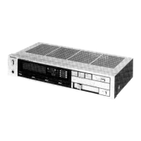
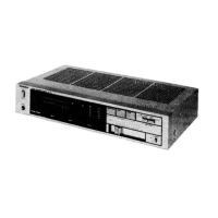
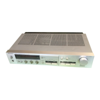
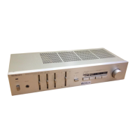
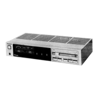
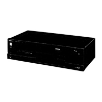
Visual breakdown of the unit's components for assembly/disassembly.

Related product manuals