EasyManuals Logo

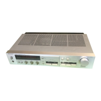
Technics SU-Z65 Service Manual

Technics SU-Z65
20 pages
To Next Page IconTo Next Page
To Previous Page IconTo Previous Page
Page #9 background imageLoading...
Page #9 background image
10.
How
to
remove
the
power
transistor
(1)
Remove
the
cabinet
and
bottom
board.
(2)
Remove
the
9
rear
panel
setscrews
(Fig.
13:
@~@
)
and
unsolder
the
power
transistor.
(3)
Remove
the
heat-sink
setscrew
(Fig.
13:
@
)
and
circlip
(Fig.
13:
@
)
to
remove
the
heat-sink.
(4)
Remove
the
3
setscrews
(Fig.
14:
@
~
@)
of
the
power
transistor
holder
to
remove
the
power
transistor.
Rear
panel
[Fig.
13]
Heat-sink
[Fig.
14]
Mi
MEASUREMENTS
AND
ADJUSTMENTS
e
Adjustment
points
Lch
Load
Reh
Load
impedance
impedance
detection
detection
ivasoi]
[vmod
onoon
Tf
|
SARL
ee
aoa
eres
ae)
a
ey
ee
aes
petty
A
Jail]
220:
z2<.|
\OMORMe
|
Power
transformer
fa
a
a
a
a
a
car
a
ar
TP301
iactey4
|
am,
CO
}
=
ee
Ld
ar
VR602
VR20I
ich
Rch
Lech
Ico
FL
meter
FL
meter
1.
Load
impedance
detection
and
idling
current
of
power
transistor
(Ica)
©
Setting
and
instruments
used
1.
Speaker
selector
2.
DC
voltmeter
Connection
of
DC
voltmeter
*Connect
a
load
with
6.52
(1/2W
carbon
resistor)
or
series-connected
3.32
and
3.32
(1/2W,
+5%)
to
the
“main”
speaker
terminal.
(Fig.
15)
*Connect
a
DC
voltmeter
between
and
chassis.
3.
Instruments
for
circuit
operation
check
(AC
voltmeter,
1kHz
oscillator,
82
load,
SW
0.332
resistor,
1/2W
6.52
or
3.32
&
3.32)
VR
adjusted
Adjustment
1.Connect
EGERE}
and
chassis.
2.
Completely
turn
VR301
and
VR302
clockwise
beforehand.
3,
Adjust
VR301
so
that
the
voltage
of
is
-0.1V]
4.
Adjust
VR302
so
that
the
voltage
of
is
OV
in
Adjustment
of
load
:
100mV
range.
pkg
*Connect
a
load
with
6.52
(1/2W
carbon
resistor)
or
circuit
series-connected
3.39
and
3.32
(1/2W,
+5%)
to
the
“main”
speaker
terminal,
(Fig.
15)
*Connect
a
DC
voltmeter
between
and
chassis.
L
channel
Connect
voltmenter
to
(+)
and
(-)
VR201
R
channel
Connect
voltmeter
to
(+)
and
(—)
VR202
2.
Check
point
®@
DC
balance
1,
Completely
turn
VR201
and
VR202
anticlockwise
beforehand
2,
Adjust
VR201(L
channel)
and
VR202
(R
channel)
so
that
the
voltage
is
0.5m\V,
about
1
min.
after
power
supply
ON.
Adjustment
of
ICQ
6.52(1/2W)
6.52
(1/2wW)
1.
Connect
DC
voltmeter
and
8Q
load
to
speaker
terminal.
be
bea
2.
Make
sure
that
output
voltage
is
within
+100mv,
Hor
3.32
3.302
3.32
3.32
[Fig.
15]
3.
Fluorescent
peak
power
meter
Setting
:
®
Connect
a
low
frequency
oscillator
to
the
tuner
input
terminal,
and
8-ohm
load
resistor
and
AC
electronic
voltmeter
to
the
speaker
terminal.
@
Add
1kHz
signal
from
the
low
frequency
oscillator
to
the
set.
@
Set
the
sound
volume
to
the
maximum
point.
1,
Adjust
the
input
level
so
that
tthe
AC
voltmeter
indicates
2
volts.
2,
Adjust
the
semi-fixed
variable
resistors
VR601
(L
ch.)
and
VR602
(R
ch.)
so
that
the
SOW
segment
of
FL
meter
lights
up
dimly.
(Fig.
16)
Peak
-power
indicators
Range
switch...
X0.01
VR601
(L
ch)
VR602
(R
ch)
x
0.01
meter
range
(8Q,
2V
output)
(Bass,
Treble
and
Balance
control
to
center)
gy
(Fig.
16]

Questions and Answers:

Question and Answer IconNeed help?

Do you have a question about the Technics SU-Z65 and is the answer not in the manual?

Technics SU-Z65 Specifications

General IconGeneral
BrandTechnics
ModelSU-Z65
CategoryAmplifier
LanguageEnglish

Related product manuals