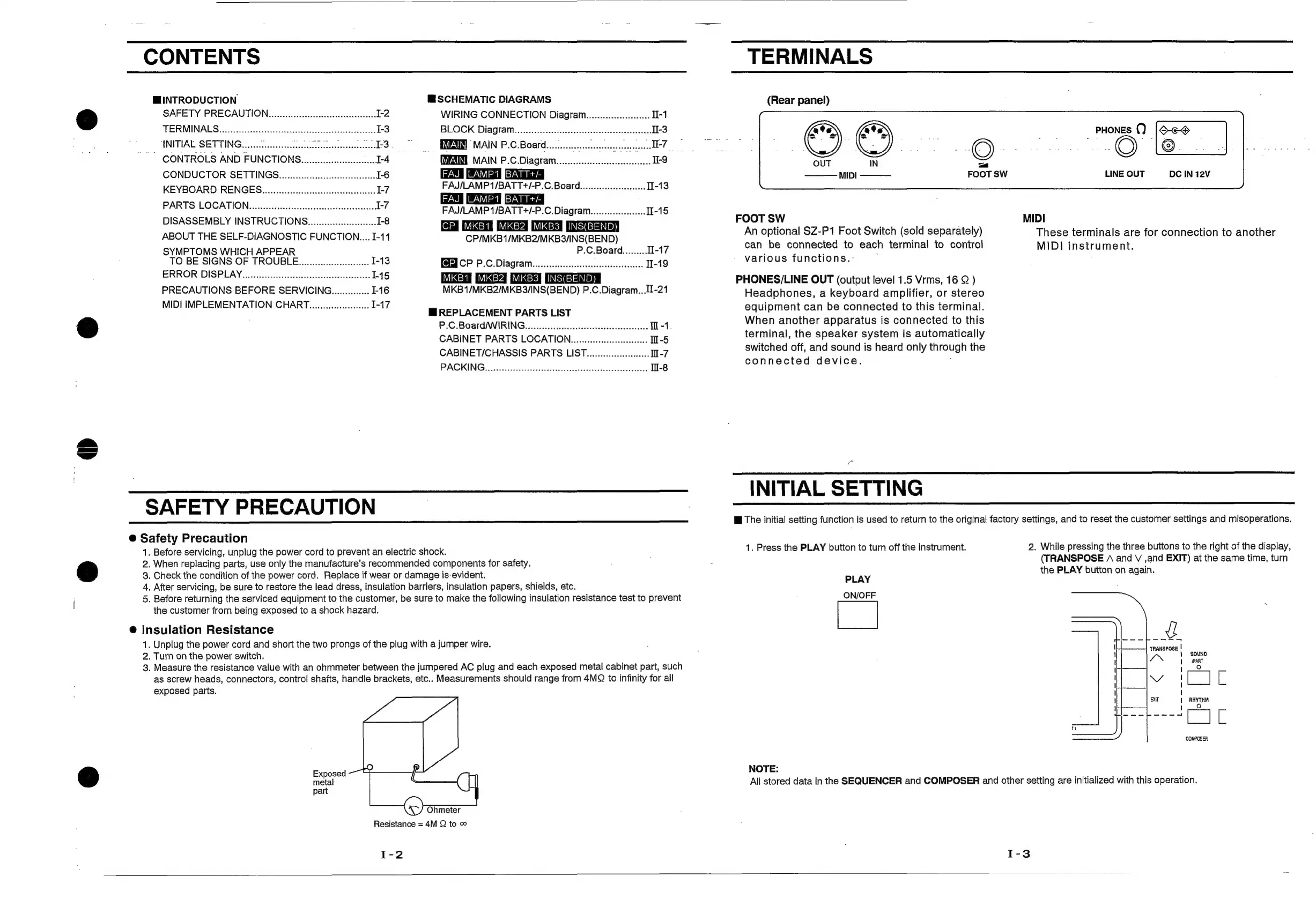
CONTENTS
INTRODUCTION
MSCHEMATIC
DIAGRAMS
SAFETY
PRECAUTION......c.ccccccsccscssesessssesesesseees
1-2
WIRING
CONNECTION
Diagram..........ccccsecees
11-1
TERMINALS
sas
pecs
eatatac
tes
cu
aed
1-3
BLOCK:
Dial
alits
ces
eveintssasvaliczess
We
edechscedeineacetes
11-3
SINITIAE,
SETTING
sas
tcntitiieeteonts
ce
eteteton
dS
MAIN:P2C
Boatds,
cisucnienmastiaascidits,
|
CONTROLS
AND
FUNCTIONS..........ccccsseeseseseees
1-4
MAIN
P.C.
Diagram...
ccc
eeeeeeeeeeees
-9
CONDUCTOR
SETTINGS
..ccccccccccccsssssssescssessseees
1-6
KEYBOARD
RENGES.iececcccsssssssssescesessssssssesesssse
ey
FAJ/LAMP
TBAT
T#/-P.C.Board.....ssssesssseeeeeeee
1-13
PARTS
LOCATION
1-7
POee
eee
eeeeICCCErererrr
rr
er
erer
rrr
ere
reer
rr
ees
FAJ/LAMP1/BATT+/-P.C.
Diagram....................01-15
DISASSEMBLY
INSTRUCTIONG....................0.6
I-8
INSEE
ABOUT
THE
SELF-DIAGNOSTIC
FUNCTION...
I-11
CP/MKB1/MKB2/MKB3/INS(BEND)
SYMPTOMS
WHICH
APPEAR
P.C.Board.........
TI-17
TO
BE
SIGNS
OF
TROUBLE.............:ccese
I-13
TERI
CP
P.C.
Diagram...
ceecceceeseseseessseesees
II-19
ERROR
DISPLAY...........:csscccsssccesscsecseeeestseeesees
145
INS(BEND)
PRECAUTIONS
BEFORE
SERVICING..............
1-16
MKB1/MKB2/MKB3/INS(BEND)
P.C.Diagram...I-21
MIDI
IMPLEMENTATION
CHART.
......ccccscceceeeee-
I-17
Mi
REPLACEMENT
PARTS
LIST
P.C.Board/
WIRING...
ccccccscsescsesscscscsescsecececscses
W-1.
CABINET
PARTS
LOCATION.....c-ccccscsccccsseeeseess
m-5
CABINET/CHASSIS
PARTS
LIST.....cccccccssssesseees
Il-7
PAGING
cc.
eeeedeionll
xx
tdaresieclcsescsaed
I-8
SAFETY
PRECAUTION
@
Safety
Precaution
1.
Before
servicing,
unplug
the
power
cord
to
prevent
an
electric
shock.
2.
When
replacing
parts,
use
only
the
manufacture’s
recommended
components
for
safety.
3.
Check
the
condition
of
the
power
cord.
Replace
if
wear
or
damage
is-evident.
4.
After
servicing,
be
sure
to
restore
the
lead
dress,
insulation
barriers,
insulation
papers,
shields,
etc.
5.
Before
returning
the
serviced
equipment
to
the
customer,
be
sure
to
make
the
following
insulation
resistance
test
to
prevent
the
customer
from
being
exposed
to
a
shock
hazard.
@
Insulation
Resistance
1.
Unplug
the
power
cord
and
short
the
two
prongs
of
the
plug
with
a
jumper
wire.
2.
Turn
on
the
power
switch.
3.
Measure
the
resistance
value
with
an
ohmmeter
between
the
jumpered
AC
plug
and
each
exposed
metal
cabinet
part,
such
as
screw
heads,
connectors,
control
shafts,
handle
brackets,
etc..
Measurements
should
range
from
4MQ
to
infinity
for
ail
exposed
parts.
Exposed
metal
part
Ohmeter
Resistance
=
4M
Q
to
©
I-2
TERMINALS
(Rear
panel)
_
PHonEs
0)
|O-e-@
—
|
Mn.
Bhi
eo
—_
MIDI
FOOT
SW
LINE
OUT
DC
IN
12V
FOOT
SW
MIDI
An
optional
SZ-P1
Foot
Switch
(sold
separately)
These
terminals
are
for
connection
to
another
can
be
connected
to
each
terminal
to
control
MIDI
instrument.
various
functions.-
:
PHONES
/LINE
OUT
(output
level
1.5
Vrms,
16
Q
)
Headphones,
a
keyboard
amplifier,
or
stereo
equipment
can
be
connected
to
this
terminal.
When
another
apparatus
is
connected
to
this
terminal,
the
speaker
system
is
automatically
switched
off,
and
sound
is
heard
only
through
the
connected
device.
;
INITIAL
SETTING
i
The
initial
setting
function
is
used
to
return
to
the
original
factory
settings,
and
to
reset
the
customer
settings
and
misoperations.
1.
Press
the
PLAY
button
to
turn
off
the
instrument.
2.
While
pressing
the
three
buttons
to
the
right
of
the
display,
(TRANSPOSE
(\
and
V
,and
EXIT)
at
the
same
time,
turn
the
PLAY
button
on
again.
PLAY
ON/OFF
U
—--_“S4
TRANSPOSE
|
1
SOUND
PART
Ve
ae
RHYTHM
COMPOSER
NOTE:
All
stored
data
in
the
SEQUENCER
and
COMPOSER
and
other
setting
are
initialized
with
this
operation.

 Loading...