INSTRUCTIONS FOR THE INSTALLER
Installation (Electrical)
These Instructions are for the authorised installer, as a guide to the installation,
adjustment and maintenance, according to the laws and standards in force. Any of
these operations must always be carried out when the appliance has been disconnected
from the electric system.
Installation (Gas)
This appliance is not provided with a combustion product discharge. It is
recommended that it be installed in accordance with the Australian Standard
AS560l/AC60l and any other local regulations or by laws. The quantity of air which
is necessary for combustion must not be below 2.0 m3/h for each kw of installed
Power.
See table of burner power.
The OPERATION of the appliance including the ignition system must be tested
before leavilig.
PF?;.£t3£)?Ti:8appliancecanbefittedintoaworkingareaasillustratedonthe
corresponding figure.
Apply the seal provided over the whole of the area perimeter.
Gas connection
(Fig. 4) Connect the appliance to the gas cylinder or to the installation according to the
prescribed standards in force, and ensure beforehand, that the appliance matches the
type of gas available. Otherwise, see "Adaptation to various types of gas".
Furthermore, check that the feed pressure falls within the values described on the
table: "User chacteristics".
Rigid/semi rigid metal connection
Carry out the connection with fittings and metal pipes (even flexible pipes) so as to
#i:I.n#tiies:Lesst:[t[t:i;nnnf:spg::Sn°cfatrhr:eapop:£t::a:.cktheperfectsealingoftheentire
connection system, by using a soapy solution.
Electrical connection
(Fig. 5) Prior to carrying out the electrical
connection, please ensure that:
•::;Ptahnattc;:::adcftceartj:i£Cosnatrfes:Cahtra;:tp°]:::-
placed at the bottom of the working area;
• that the plant is fitted with an efficient
earth connection, following the standards
and law provisions in force. The earth
connection is compulsory in terms of the
law.
•ffi:S8:£t8,,tFR,
Fig. 4
Should there be no cable and /or plug on
the equipment, use suitable absorption material for the working temperature as well,
as indicated on the matrix plate. Under no circumstance must the cable reach a tem-
peratureabove50°Coftheambienttemper3ture.
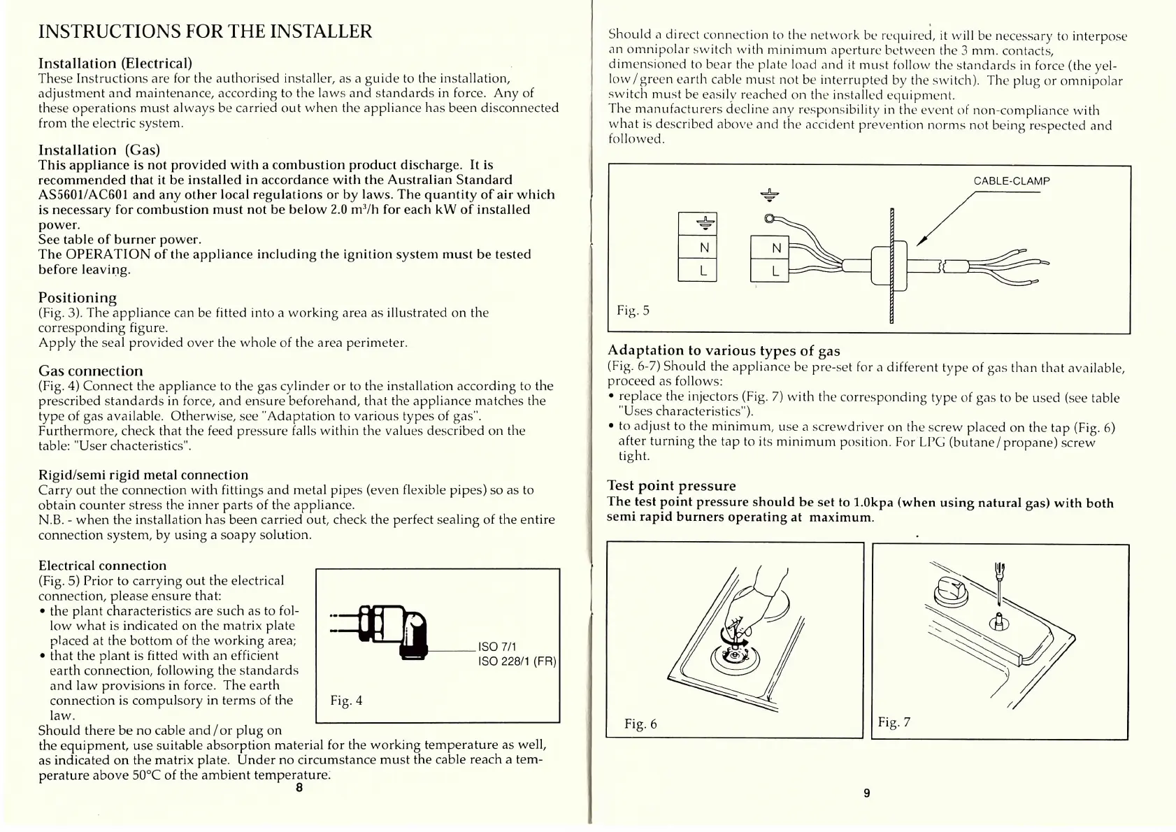
Should a direct connection to the network be reqiiired, it will be necessary to interpose
an omnipolcir switch with minimum ciperture between the 3 mm. contacts,
dimensioned to becir the plate locid cilid it must follow the standards in force (the yel-
low/green earth cable must not be interrupted by the switch). The plug or omnipolar
switch must be easily reached on the instcilled equipment.
Tlie maniifacturers decline ciny responsibility in the event of non-compliance witli
what is described above and the ciccident prevention norms not being respected and
followed.
Adaptation to various types of gas
(Fig. 6-7) Should the applicince be pre-set for a different type of gas than thcit available,
proceed as follows:
• replace the injectors (Fig. 7) with tlie corresponding type of gcis to be used (see table
"Uses characteristics").
• to adjust to the minimiim, use a screwdriver ()n the screw placed on the tap (Fig. 6)
after turning the tap to its minimum position. For LPG (butane/propane) screw
tight.
Test point pressure
The test point pressure should be set to 1.Okpa (when using natural gas) with both
semi rapid burners operating at maximum.
 Loading...