Do you have a question about the Tecnoalarm TP16-256 and is the answer not in the manual?
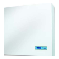
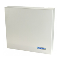
Details the hardware components of the control panel, including power supply, casing, inputs, outputs, control units, and interfaces.
Outlines the primary functions and capabilities of the TP16-256 system, including codes, timers, and programming features.
Describes the components of the TP16-256 control panel, including the CPU board, casing, and connected modules via serial bus.
Details the physical connection procedures for the control panel, including wall mounting and mains power connection.
Describes the SPEED ALM8 PL input expansion module, its composition, and connection details.
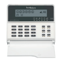
Details the LCD300/S console, its composition, LED signaling, and serial line diagnostics for system interaction.
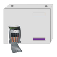
Explains the TP SDN electronic keypad, its function for control, and its electronic board components for serial bus connection.
Details the ESP32-OCN output expansion module, its electronic board, and casing for system status signaling.
Describes the PROG32 interface for connecting the control panel to a PC for programming, firmware, and vocabulary upgrades.
Details the TECNOCELL-PRO PL telephone communicator with GSM module for sending alarm signals via GSM network.
Describes the RTX200/433868 wireless receiver-transmitter for data transmission via RS485 serial bus.
Outlines the importance of planning the installation on paper to ensure a smooth system setup and component accessibility.
Guides the user through configuring the system hardware using the Tecnoalarm programming software on a PC.
Explains how to create and configure zone lists, associating physical inputs with logical zones for alarm detection.
Provides preliminary information on console programming, available commands, and operational remarks for the installer.
Details the recommended sequence for programming the control panel via console, covering various sections and parameters.
Explains how to arm the control panel using programs, master code, standard user code, key zone, or timers, including status checks.
Details how to control the system using the TP SK6N key reader with mini keypad, including arming, disarming, and by-pass functions.
Provides detailed technical specifications for the TP16-256 control panel, including power supply, consumption, and component details.
Outlines the procedure for resetting all system codes to their default values, including installer, master, and user codes.
Details the process for performing a full system reset, restoring all settings to factory defaults.
Explains how users can modify their own codes if the system setting allows, ensuring individual code security.
| Brand | Tecnoalarm |
|---|---|
| Model | TP16-256 |
| Category | Control Panel |
| Language | English |