EN |
EVO
SELF
| User and Maintenance Manual
36
ALARMS
Label Fault Cause E ects Remedy
E1
Probe1 faulty
(cold room)
• reading of out of range operating values
• probe faulty / short-circuited / open
• Display label E1
• Alarm icon permanently ON
• Min/max alarm regulator disabled
• Compressor operation according to “Ont”
and “OFt” parameters.
• check probe type (NTC)
• check the probe wiring
• replace probe
E2
Probe2 faulty
(defrost)
• reading of out of range operating values
• probe faulty / short-circuited / open
• Display label E2
• Alarm icon permanently ON
• The defrost cycle will end due to Time out
(Parameter “dEt”)
• check probe type (NTC)
• check the probe wiring
• replace probe
AH1
Probe1 HIGH
Temperature alarm
• value read by Pb1 > HAL after time
of “tAO”. (see “MIN/MAX ALARMS table)
• Registration AH1 label in the AL folder
• No e ect on regulation
• Wait until temperature value read by probe1
returns below HAL.
AL1
Probe1 LOW
Temperature alarm
• value read by Pb1 < LAL after time
of “tAO”. (see “MIN/MAX ALARMS table)
• Registration AL1 label in the AL folder
• No e ect on regulation
• Wait until temperature value read by probe1 to
come back obove LAL
EA External alarm
• Digital input activated (H11 set as external
alarm)
• Registration EA label in the AL folder
• Alarm icon permanently ON
• Regulation blocked if EAL = y
• check and remove the external cause which
generate alarm on D.I.
OPd Door Open alarm
• Digital input activated (H11 set as door switch)
(for a longer time than tdO)
• Registration Opd label in the AL folder
• Alarm icon permanently ON
• Regulator blocked
• close the door
• delay function de ned by OAO
Ad2
Defrosting
for time-out
• end of defrosting because of time instead of
because of reaching the defrost end temperature
detected by the Pb2 probe.
• Registration Ad2 label in the AL folder
• Alarm icon permanently ON
• wait until the next defrost for automatic return
MANUAL DEFROST CYCLE ACTIVATION
To manually activate the defrost cycle, hold down the key for 5 seconds.
If the defrost conditions are not satisfi ed:
- the parameter OdO ≠ 0 (EW961, EW971 and EW974)
- the evaporator probe Pb2 temperature is higher than the defrost end temperature (EW971 and EW974) the display will fl ash 3 times, to indicate
that the operation will not be carried out.
DIAGNOSTICS
Alarms are always indicated by the buzzer (if present) and the alarm icon .
To switch off the buzzer, press and release any key, the relative icon will continue to fl ash.
NOTES: If alarm exclusion times have been set (see ‘AL’ folder in the parameters table) the alarm will not be signalled.
A probe 1 (Pb1) malfunction alarm will appear directly on the display with the
indication E1.
Models EW971 and EW974: A probe 2 (Pb2) malfunction alarm will appear
directly on the display with the indication E2.
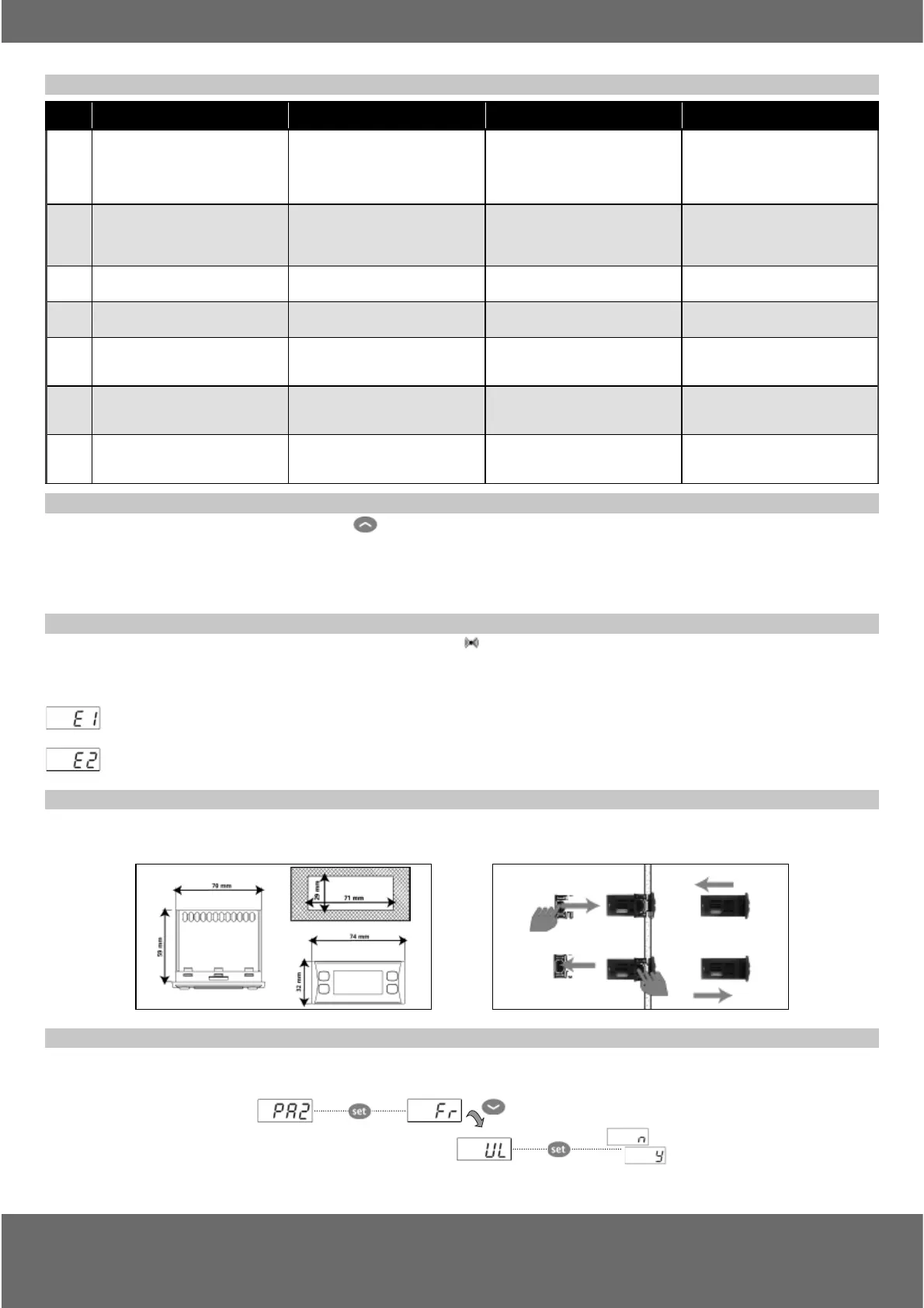
DIAGNOSTICS
The instrument is designed for panel mounting. Make a hole of 29x71 mm, insert the instrument and fi x it using the brackets provided. Do not
mount the instrument in humid and/or dirty places; it is suitable for use in ordinary polluted places. Ventilate the place in proximity to the instru-
ment colling slits.
USING THE COPY CARD
The Copy Card is an accessory connected to the TTL serial port used for quick programming of the device parameters (upload and download a
parameter map to one or more devices of the same type). Upload (label UL) and copy card formatting (label Fr) operations should be performed
as explained below: