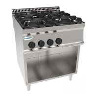
This document describes a range of gas cooktops, including models PC35G7, PC70G7, PC105G7, PCP70G7, PCP105G7, and PPC70G7. These appliances are designed for professional use in kitchens, specifically for cooking food. Any other use is considered improper.
Function Description
The cooktops are gas-powered appliances designed for professional cooking. They feature multiple burners and, in some models, a hot plate. The burners are made of cast iron, while the oven (if present) and the overall structure are stainless steel. All models are equipped with height-adjustable feet. The main gas pipe is galvanized steel, and the connections from the tap to the burners are copper.
The appliances operate by pressing and turning a knob (labeled "A" in Fig. 3) to the "flame on pilot light" position. The pilot light can be ignited using an igniter (labeled "W" in Fig. 2) or a match. Once the pilot flame is lit, the knob must be held down for approximately 10 seconds (counting to twenty) to allow the thermocouple to heat up and keep the safety valve open. For models with a hot plate, the cover (labeled "C" in Fig. 2) must be lifted first. The PPC70G7 model specifically uses an igniter button (labeled "B" in Fig. 3) for pilot light ignition. To light the main burner, the knob is turned further to the desired position.
To turn off a burner, the knob is rotated to the "off" position. To turn off the entire appliance, the knob is rotated to the "off" position. If the piezoelectric igniter cannot be used, the flame can be lit manually with a match or gas lighter.
Important Technical Specifications
The appliances comply with UNI EN 203 and UNI EN 437 standards.
The self-adhesive polyester data plate (labeled "T" in Fig. 2), located behind the control panel, provides the following information:
- Model: PC35G7, PC70G7, PC105G7, PCP70G7, PCP105G7, PPC70G7
- Serial number: XXXXXX
- Category: II2H3+
- Year of construction: XXXX
- Nominal thermal capacity:
- PC35G7: 10.5 kW
- PC70G7: 19.5 kW
- PC105G7: 30 kW
- Type of construction: A
- Test base: UNI EN 203-1
- Connection pressure:
- G30: 28-30/37 mbar
- G20: 20 mbar
- Consumption:
- Metano (G20) - (Hi = 9.45 kWh/m³):
- PC35G7: 1.11 m³/h
- PC70G7: 2.06 m³/h
- PC105G7: 3.17 m³/h
- PCP70G7: 1.59 m³/h
- PCP105G7: 2.41 m³/h
- PPC70G7: 0.95 m³/h
- Metano (G25 - G25.1) - (Hi = 8.13 kWh/m³):
- PC35G7: 1.29 m³/h
- PC70G7: 2.40 m³/h
- PC105G7: 3.69 m³/h
- PCP70G7: 1.84 m³/h
- PCP105G7: 2.80 m³/h
- PPC70G7: 1.10 m³/h
- GPL (G30) - (Hi = 12.68 kWh/kg):
- PC35G7: 0.83 kg/h
- PC70G7: 1.54 kg/h
- PC105G7: 2.37 kg/h
- PCP70G7: 1.82 kg/h
- PCP105G7: 1.79 kg/h
- PPC70G7: 0.71 kg/h
The supplementary plate, also made of self-adhesive polyester, contains all information regarding the appliance's setup.
The gas distribution network connection (labeled "G" in Fig. 1) complies with ISO 7/1 and ISO 228/1 (DK) standards, with a ø 1/2" connection, located at the bottom of the machine.
Usage Features
Installation:
- The appliance must be installed by qualified personnel according to local regulations and the instructions provided.
- It is recommended to install the appliance under an extractor hood to remove cooking fumes.
- A shut-off cock must be installed between the appliance and the gas distribution network.
- Maintain a minimum distance of 80mm between the appliance and any flammable walls, partitions, kitchen furniture, or adjacent equipment. Contact surfaces must be covered with non-combustible heat-insulating material.
- The appliance should not be installed near heat sources, and the ambient temperature should not exceed 50°C.
- After installation, check for gas leaks using non-corrosive foam products. Do not use naked flames for leak detection.
Gas Type Conversion:
- To convert the appliance from one gas type to another (e.g., natural gas to LPG), the nozzles of the main burner, bypass, and pilot light must be changed. All nozzles are marked with a number indicating their diameter in 1/100 and are supplied in a bag.
- After conversion, the appliance must undergo an operating test, and the supplementary plate must be updated.
- Burner Nozzle Replacement: Pull off the knobs, remove the control panel by unscrewing the fixing screws, and locate the burners. Replace nozzle "U" (Fig. 4) with the appropriate one for the new gas type, as indicated in the "MAX" nozzles table T1 section. Repeat for all burners.
- Air Adjustment: Loosen fixing screw "X" (Fig. 4). Adjust the primary air by moving the bush to distance "H" (Fig. 6), as indicated in the nozzles table T1 section. Tighten fixing screw "X" (Fig. 4) to block the bush.
- Pilot Light Nozzle Replacement: Unscrew and remove closing nut "Z" (Fig. 4). Unscrew and replace the pilot nozzle "D" (Fig. 4) with the type indicated in the nozzles table T1 section. Replace and tighten closing nut "Z" (Fig. 4).
- Minimum Flame Adjustment: Unscrew and replace or adjust nozzle "Um" (Fig. 5) based on the indications in the nozzles table T1 section. Reassemble the control panel and knobs.
Pressure Check:
- The distribution network pressure must be within the allowed range (e.g., LPG: 20/25 to 35/45 mbar; Methane H: 17 to 25 mbar).
- Pressure can be measured using a U-manometer connected to the pressure outlet "H" (Fig. 5) behind the control panel.
- Remove the control panel, then screw "Y" and the sealing washer (Fig. 5) from the pressure outlet and connect the manometer.
- Turn on the appliance and check if the measured pressure is within the permitted range.
- Disconnect the manometer and replace screw "Y" and the sealing washer. Reassemble the control panel.
Flame Appearance:
- The flame should be blue, without yellow tips, and stable at its base.
- A yellowish flame indicates improper primary airflow adjustment.
- If primary airflow is too fast, the flame will be short and tend to lift off the burner.
- Check flame appearance after approximately 15 minutes of full power operation. The flame must remain stable even when quickly transitioning from minimum to maximum.
Malfunctions:
- In case of suspected abnormal functioning, turn off the appliance and disconnect it from the mains. Call authorized repair service.
- Unauthorized persons should not attempt repairs; tampering voids the warranty.
Long Periods of Inactivity:
- Close the upstream gas shut-off cock.
- Clean the appliance with soapy water, rinse, dry thoroughly, and apply a light layer of liquid paraffin.
Maintenance Features
Cleaning:
- Cleaning must only be performed when the appliance is cold.
- Regular cleaning is crucial for proper functioning and longevity.
- Removable parts (e.g., drawer "V" in Fig. 2) should be washed separately with hot water and detergent, then rinsed with running water.
- Stainless steel parts can be cleaned with a damp cloth and a non-abrasive detergent, then wiped dry with a soft cloth. For stubborn stains, use hot water and vinegar.
- Do not use aggressive or abrasive detergents, metal scourers, sandpaper, or steel wool on stainless steel parts, as this can cause rust or scratches. Avoid contact with ferrous materials.
- For persistent dirt, use sponges (e.g., Scotch-Brite) or oven/grill spray cleaners, following the manufacturer's instructions.
General Maintenance:
- The appliance does not require special maintenance beyond normal cleaning.
- An annual check by a qualified technician is recommended; a maintenance contract is advisable.
- All parts that come into contact with food during use must be cleaned regularly.
Safety Warnings:
- The appliance must always be used under supervision.
- Surfaces become very hot during operation; exercise caution.
- Only qualified personnel should operate the appliance.
- Installation, conversion, or adaptation to a different gas type must only be performed by qualified and authorized personnel according to legal requirements.
- In case of fire, immediately close the gas shut-off cock and use an appropriate fire extinguisher.
Environmental Protection:
- The appliances are designed for high performance and efficiency. To reduce energy consumption, avoid prolonged empty operation or use under suboptimal conditions.
- All packaging materials are environmentally friendly and can be safely stored or incinerated in appropriate waste facilities. Plastic components (polyethylene, polypropylene, expanded polystyrene) are recyclable.
- At the end of its life, the appliance should be disposed of properly. Over 90% of the appliance is made of recyclable metal (stainless steel, iron, aluminum), which can be processed through traditional recycling structures.
- To render the appliance unusable before disposal, cut the power cable and remove any locking devices to prevent entrapment.