
L
Lisa MartinJul 31, 2025
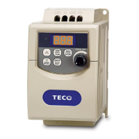
What to do if TECO-Westinghouse Motor Inverter is overheating during stop?
- AAna JamesJul 31, 2025
If your TECO-Westinghouse Motor Inverter is overheating during stop, it could be due to a thermal detection circuit malfunction, in which case you should repair or replace the unit. Alternatively, the ambient temperature might be too high, or ventilation might be poor. To resolve this, try improving ventilation conditions or relocating the inverter.