EasyManua.ls Logo

TECO-Westinghouse Motor MA7200 User Manual

TECO-Westinghouse Motor MA7200
153 pages
To Next Page IconTo Next Page
Page #1 background imageLoading...
Page #1 background image
4H358D0180009
Installation Manual
MA7200
AC Inverter
208 to 230V 1 / 3 Phase 1 ~ 3HP
3 Phase 5 ~ 40HP
380 to 460V 3 Phase 1 ~ 75HP

Table of Contents

Question and Answer IconNeed help?

Do you have a question about the TECO-Westinghouse Motor MA7200 and is the answer not in the manual?

TECO-Westinghouse Motor MA7200 Specifications

General IconGeneral
BrandTECO-Westinghouse Motor
ModelMA7200
CategoryInverter
LanguageEnglish

Summary

SAFE OPERATION NOTES

WARNING and CAUTION

Defines warning and caution levels for safety.

1. MA7200 Handling Description

1.1 Inspection Procedure upon Receiving

Procedure for checking the inverter upon receipt.

1.2 Installation

Guidelines for installing the inverter.

1.3 Removing/Attaching the Digital Operator and Front cover

Steps for removing and attaching operator and cover.

1.4 Wiring between Inverter and Peripheral devices and notice

Instructions for connecting devices and important notices.

1.5 Description of terminal function

Explanation of main and control circuit terminal functions.

1.6 Main Circuit Wiring Diagram

Diagram illustrating the main circuit wiring.

1.7 Wiring main circuit and notice

Details on wiring the main circuit and notices.

1.8 Inverter Specifications

Technical specifications of the inverter.

1.9 Dimensions

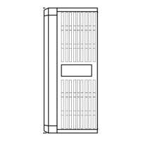
Physical dimensions of the inverter.

1.10 Peripheral Units

Information on peripheral units like braking resistors.

2. Using LCD Digital Operator

Functions of LCD digital operator

Details on the functions and modes of the LCD operator.

Remote/Local switch function

How to switch between local and remote control modes.

3. Parameter Setting

3.1 Frequency command (in Multi-speed operation)

Setting frequency commands for multi-speed operation.

3.2 Parameters Groups Can Be Changed during Running

Parameters adjustable while the inverter is running.

3.3 Control Parameters Cn-□□

Detailed control parameters for inverter operation.

3.4 System Parameters Sn-□□

System parameters for configuration and operation modes.

3.5 Monitoring parameters Un-□□

Parameters for monitoring inverter status and performance.

4. Fault display and troubleshooting

4.1 General

General overview of fault and warning functions.

4.2 Error Message and Troubleshooting

Detailed list of error messages and troubleshooting steps.

A. Adjusting PID Controller

C. Wiring for PG Feedback Use

D. RS-485 Communication Interface

E. SINK/SOURCE Typical Connection Diagram

F. RS-232C Serial Communications Connection Diagram

G. Sensorless Vector Control Set-up

H. Notes for Circuit Protection and Environmental Ratings

Related product manuals