Do you have a question about the TECO-Westinghouse E510 and is the answer not in the manual?
Ensure correct wiring, careful handling, fire prevention, and adequate ventilation. Avoid operating with wet hands.
Wiring must be by qualified personnel. Turn off power before wiring. Ensure proper grounding. Do not perform dielectric voltage tests.
Verify inverter capacity matches parameters. Reduce carrier frequency for long cables. Install covers before power on.
Install covers before power on. Do not connect/disconnect motor during operation. Beware of sudden starts after alarm reset.
Wiring precautions: Do NOT remove covers while power is applied. Connect all wiring before applying power. Wait 5 mins after power off.
Describes keypad display, LED indicators (Hz/RPM, FWD, REV, FUN), and the 8 function keys.
Lists parameter groups (00-15) and their descriptions, with notes on adjustability and availability.
Details basic parameters: Control Mode, Run Command Source, Frequency Command Source, and acceleration/deceleration times.
Configures momentary power loss restart, auto restart attempts, reset modes, direct running on power up, and DC brake.
Defines trip prevention, over voltage, motor overload, over torque, fire mode, and ground fault protection settings.
Details PID parameters: target value, feedback value, mode selection, proportional, integral, and derivative gains.
Sets the frequency command source: keypad, external signals, communication, or PID.
Configures analog input (AI1/AI2) for 0-10V or 4-20mA signals as speed reference, including potentiometer setup.
Sets speed reference via serial communication (RS485 Modbus RTU). Includes default settings and register info.
Sets the operation command source: Keypad, External Terminal, Communication, or PLC.
Describes using RUN and STOP keys on the keypad for forward/reverse operation and stopping the inverter.
Explains using external contacts/switches for Run/Stop and Forward/Reverse commands, detailing 2-wire operation.
Details controlling Run/Stop via serial communication (RS485 Modbus RTU), including command registers for FWD/REV.
Sets motor rated power (02-05) and rated current (02-01) based on the motor's nameplate for proper operation.
Sets acceleration and deceleration times for output frequency from 0 to maximum frequency and vice versa.
Explains PID control basics: maintaining process variables by regulating output frequency using feedback.
Lists causes and solutions for faults: Over Voltage (OV), Under Voltage (LV), Overheat (OH), EEPROM, CT Fault.
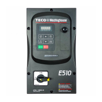
| Series | E510 |
|---|---|
| Input Frequency | 50/60 Hz |
| Output Frequency | 0-400 Hz |
| Cooling Method | Forced air cooling |
| Output Voltage | 3-Phase 0-Input Voltage |
| Power Rating | 0.75 to 630 kW (depending on model) |
| Overload Capacity | 150% for 60 seconds |
| Braking Unit | Built-in or external |
| Control Method | V/F control, Sensorless Vector Control |
| Protection Functions | Overcurrent, Overvoltage, Undervoltage, Overheat, Short Circuit |
| Communication | Modbus RTU |
| Operating Temperature | -10°C to +50°C |
| Humidity | Less than 95% RH (non-condensing) |
| Altitude | Below 1000m without derating |