11
33. Do not start the grinder holding the wheel with your hands.
34. Do not force the tool while you’re working.
ATTENTION – SETTING UP THE GRINDER - the grinder shall only be used in a place protected from dust and dampness, well-lighted,
away from children, gases, or other flammable or explosive liquids. The grinder shall be placed near a suitable earthed outlet, not to
use dangerous extension cables.
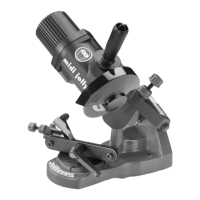
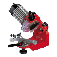
- fasten the grinder onto the bench (photo 1 ) or to the wall (photo 2) with two M8 bolts (not provided). For fastening the grinder onto a
bench, carefully position it, using the relevant reference notches.
- when the grinder is fastened onto the bench or to the wall (photo 2) use a suitable square support (not provided), making sure that the
machine is not fastened at the level of the operator’s eyes. We recommend that you install the grinder at a max. height of 120-130cm
from ground level.
- insert screw M6x25 provided, making it slide up to the end of its seat on the arm (photo 3)
- screw the handle provided on screw M6x25, checking that the screw is still at the end of its seat. If not, the wheel guard cannot be installed
(photo 4)
- after installing the grinder properly, assemble the wheel.
ASSEMBLY AND WARNINGS ABOUT THE GRINDING WHEEL:
- use a wheel fit for the type of chain to be ground, consulting the chain table enclosed at the end of the handbook (column I - L)
- before using the machine, check that the grinding wheels are in perfect condition. To do so, hang the wheels by the central hole and
tap them lightly with a non-metal object on the side near the perimeter. If they are in perfect condition you should hear a metallic sound.
A dull sound means that the wheel is cracked or broken, and shall be replaced.
- do not force the grinding wheel on the hub and do not modify the diameter of the assembly hole. Be careful not to use grinding wheels
which do not perfectly match the machine
- to install the wheel, use only clean and perfect hub and ring nut
- make sure that the outside diameters of the hub/ring nut are identical (fig. 1)
- the hub is steadily fastened onto the electrical motor’s shaft
- unscrew the ring nut manually, center and install the wheel on the hub, and re-screw the ring nut manually (photo 5)
- be careful with the ring nut assembly, since its discharge must be on the wheel side (fig. 2)
- if the grinding wheel’s ring nut is too tightened, the wheel could break or disintegrate during operation, seriously damaging the operator.
To avoid this risk, do not overtight, since this ring nut is made of thermoplastic material
- position the wheel guard on the motor casing properly, inside its seat (photo 6), and secure it in the position provided on the casing
(photo 6)
CHECKING THE GRINDING WHEEL:
- stand beside the wheel, start the grinder, and examine it to ensure that it does not oscillate either laterally or transversally, creating any
anomalous vibration
- if the wheel oscillates, immediately stop the machine and make sure that the wheel has been assembled properly. If necessary, replace
the wheel with an original spare part
- with the machine off, check the wheel profile by means of the special orange template (fig.3 point C)
- if necessary, after wearing suitable goggles and gloves, start the grinder and retouch the wheel profile with the dressing stone provided,
working carefully, grasping the dressing stone with two hands. The contact with the grinding wheel revolving at high speed could cause
burns and injuries
- before initiating grinding operations, test the assembled grinding wheel at working speed for at least one minute, keeping far from the
machine and checking that nobody is standing on the trajectory of its rotation plane.
N.B.: Replace the grinding wheels when their minimum diameter is about 80mm (3.14 inches)
START-UP:
- after fastening the machine onto the bench or to the wall, properly install the wheel, its guard, and the handle, make sure that the direction
of rotation of the wheel is the one indicated on the wheel guard; then, start up the machine
- the machine is equipped with a safety switch with a release coil, i.e. in case of sudden power failure, this switch is deactivated, leaving
the machine on stand-by in case of a sudden return of current (to restart the grinder, push the switch again)
- the machine must be connected with an outlet that ensures a 230Vac voltage or to a U.S. outlet that ensures 120Vac voltage and 10A
current
GRINDING:
- clean the chain before grinding it
- since this grinder has a fixed angle for the wheel inclination, the upper cutting angle of the tooth is fixed at 60° (measured anticlockwise)
- position the chain to be ground on the two jaws, making sure that the depth gauge is on the right, as indicated (photo 7-points 1)
- loosen the ring nut at the back of the grinder (photo 7 – point 2), and turn the vise clockwise, considering the grade that corresponds
to the upper grinding angle of the right tooth, using the graduated scale (photo 7 – point 3)
- make one of the right teeth hit the chain stop, and, with the register screw (photo 8 – point 1), adjust the tooth feeding
- the chain stop is installed on a pin installed on a plastic connecting rod. This pin has two position notches, so that the chain stop can be
positioned just at the center of the tooth to be ground
- stop the motor and lower the arm; then, with the chain feed register screws, try to approach the tooth to the wheel, until it is slightly
touched, always starting from the worst tooth identified using the template (fig. 3 point D)
- start the grinder and, with the tooth feed register screw, determine the quantity to be removed
- after determining the quantity to be removed, lock the register screw with the ring nut (photo 8 – point 2)
- to avoid overloading the motor and to prevent the chain from being damaged, remove minimum quantities of material and do not
work too long on the same tooth, so as not to damage the cutter
- adjust the grinding depth with the register screw positioned on the arm, without nicking connecting links (photo 9)
- after determining the grinding depth, lock the register screw with the ring nut (photo 9 – point 1)
- adjust the clamping lever; press the red push-button and pull the lever. The correct tightening of both jaws (photo 10) is set by a
slight clockwise rotation (clockwise rotation increases tightening, whilst anti-clockwise rotation loosen it). The tightening system with
clamping lever allows a uniform deformation of the two chain support jaws, so that the chain is always positioned just at the center
of the vise rotation. This is an essential requirement for perfect grinding, because the length of the right and left teeth must be the
same.
- if the clamping lever is turned clockwise, the chain is locked between the two jaws, for precise and safe grinding (photo 11)
- grind all teeth of the same type (right) before turning the vise on the opposite side, to start grinding left teeth (photo 12),
without touching
the chain feed register screw (photo 8 – point 1)
 Loading...