Lead resistance errors are compensated for in 3-wire configurations.
However full compensation requires equal resistance in each lead. This
configuration is common with 100-ohm RTDs.
In 4-wire configurations, accuracy is unaffected by lead resistance, and
resistance differences between leads.
NOTE: These instruments measure input voltages on all 4 termi-
nals, and are able to distinguish between 2-4 and 3-wire hookups.
Switching between these measurement modes is automatic.
2. Set instrument to METER mode.
3. Use the Sensor-Select key to set the instrument to the appropriate func-
tion and range.
NOTE: Due to limited display area, 100Ω and 1000Ω RTD's are
indicated on the display by a momentary readout of "RTD-100"
(or "RTD-1000") when first selected.
Thermistors are identified by a momentary alpha-numeric readout
of "Y-400" (signifying YSI Series-400 type thermistor).
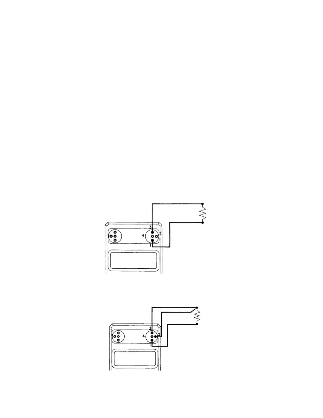
Figure 4. 2-Wire Resistance Measurement
Figure 5. 3-Wire Resistance Measurement
14
(RTD, Thermistor, etc.)
 Loading...