Operating Instructions-2225 Service
LlNE FUSE
The instrument fuse holder is located on the rear
panel and contains the line (main) fuse. Use the
following procedure to verify that the proper fuse is
installed or to install a replacement fuse.
1.
Unplug the power cord from the power-input
source (if plugged in).
2. Press in the fuse-holder cap and release it with
a slight counterclockwise rotation.
3.
Pull the cap (with the attached fuse inside) out
of the fuse holder.
NOTE
The two types of fuses listed on the rear
panel are not directly interchangeable; they
require different types of fuse caps.
4.
Verify that the fuse is the same type listed on
the back of the instrument.
5.
Reinstall the fuse (or replacement fuse) in the
fuse-holder cap.
6.
Reinstall the fuse and cap in the fuse holder by
pressing in and giving a slight clockwise rotation
of the cap.
POWER CORD
A detachable three-wire power cord with a three-
contact plug is provided with each instrument for
connecting to both the power source and protective
ground. The protective-ground connector in the
plug connects (through the protective-ground con-
ductor) to the accessible metal parts of the instru-
ment. For electrical-shock protection, insert this
plug only into a power-source outlet that has a
properly grounded protective-ground contact.
Un~versal
%\
1
2r
1
240v
1
CEE IEC 83 F'Lll,lV.Vll
1
;;
1
10-16A
8s 1363
240v'
"''
IEC 83
13A
Option
Number
Z
Reference
Standards
Line
Voltage
Plug
Configuration
North
ran
120v/
15A
North
Amerncan
240V/
15A
Abbreviations:
ANSl
-
American National Standards Institute
AS
-
Standards Association of Australia
BS
-
British Standards Institution
CEE
-
International Commiss~on on Rules for the
Approval of Electrical
Equ~pment
IEC
-
International Electrotechnical Comm~ssion
NEMA
-
National Electrical Manufacturer's Association
(2931 -21
)6083-35
Usage
Sw~tzerland
220V/
6A
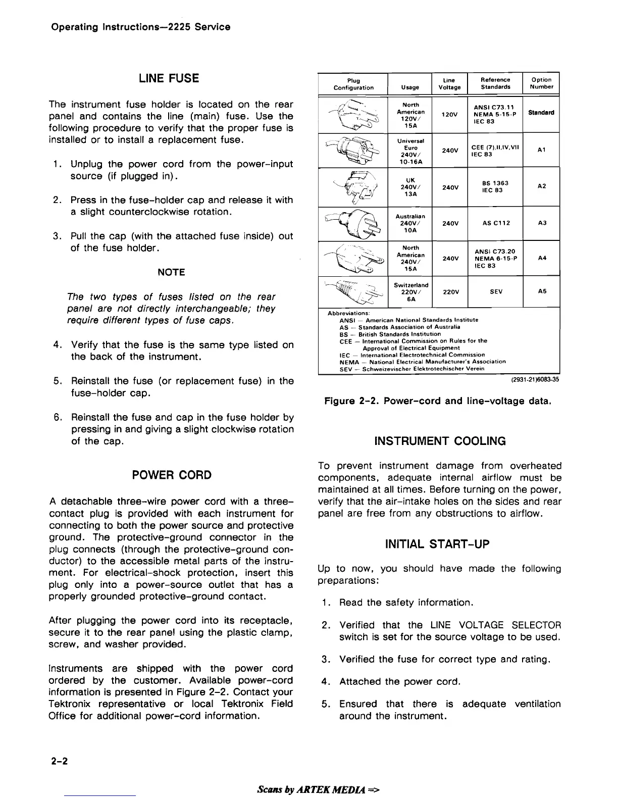
Figure 2-2. Power-cord and line-voltage data.
120~
240V
INSTRUMENT COOLING
220V
To prevent instrument damage from overheated
components, adequate internal airflow must be
maintained at all times. Before turning on the power,
verify that the air-intake holes on the sides and rear
panel are free from any obstructions to airflow.
ANSI C73 11
5.15.~
IEC 83
ANSl C73 20
NEMA 6-15 P
IEC 83
INITIAL START-UP
Standard
A4
SEV
Up to now, you should have made the following
preparations:
A5
1.
Read the safety information.
After plugging the power cord into its receptacle,
2.
Verified that the LlNE VOLTAGE SELECTOR
secure it to the rear panel using the plastic clamp,
switch is set for the source voltage to be used.
screw, and washer provided.
3.
Verified the fuse for correct type and rating.
Instruments are shipped with the power cord
ordered by the customer. Available power-cord
4.
Attached the power cord.
information
is
presented in Figure 2-2. Contact your
Tektronix representative or local Tektronix Field
5.
Ensured that there is adequate ventilation
Office for additional power-cord information.
around the instrument.
Scans
by
ARTEK
MEDCQ
=>
 Loading...