Product: 2225 SERVICE Date: 8-1-88 Change Reference:
C110888
DESCRIPTION
0.
Turn power off on the DC power supply and recon-
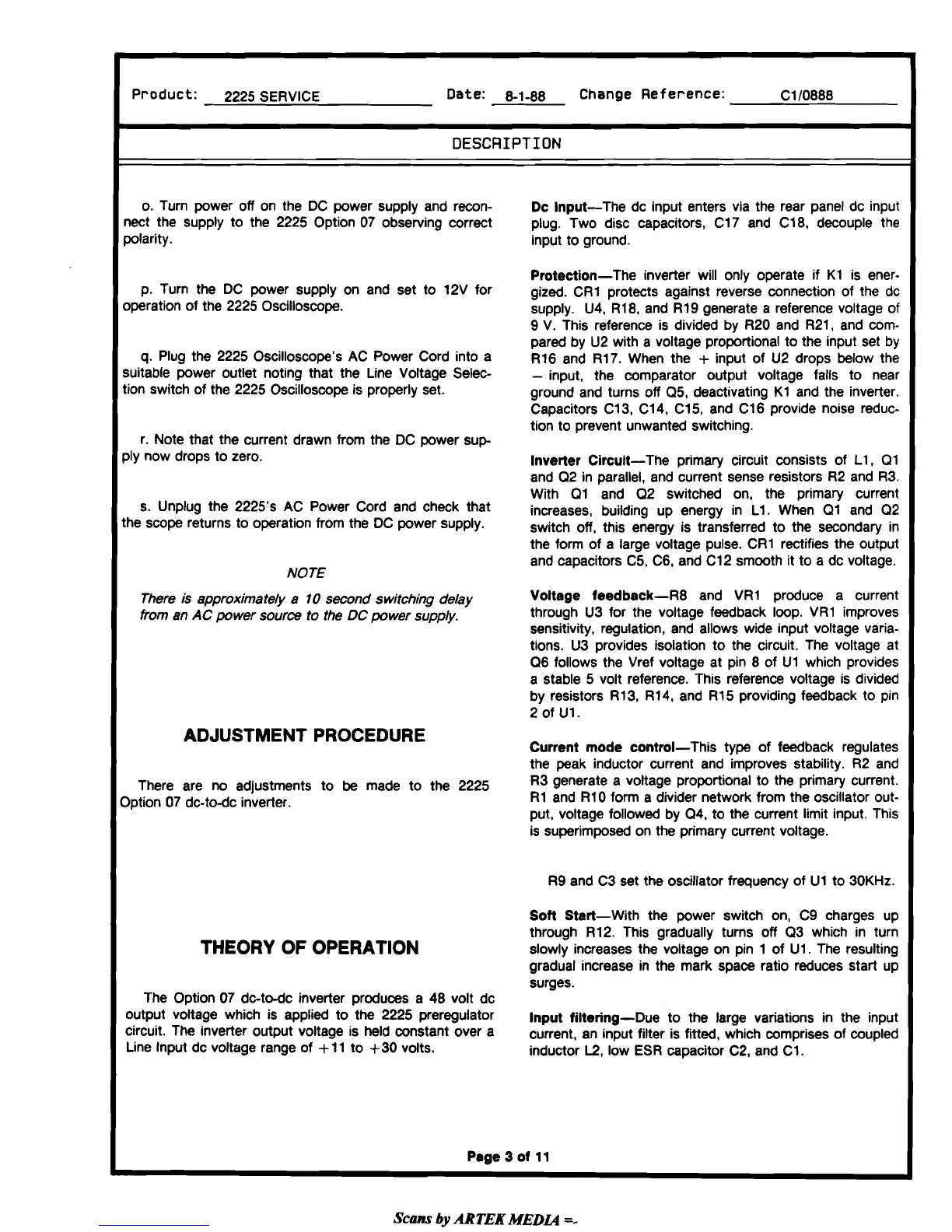
Dc Input-The dc input enters via the rear panel dc input
nect the supply to the 2225 Option 07 observing correct
plug. Two disc capacitors, C17 and
C18, decouple the
polarity. input to ground.
Protection-The
inverter will only operate if K1 is ener-
P. Turn the DC power Supply on and set to 12V for
gized.
CR1 protects against reverse connection of the dc
operation of the 2225 Oscilloscope.
supply. U4,
R18, and R19 generate a reference voltage of
9 V. This reference is divided by R20 and
R21, and com-
pared by U2 with a voltage
proportional to the input set by
q.
Plug the 2225 Oscilloscope's AC Power Cord into a
R16 and R17. When the
+
input of U2 drops below the
suitable power outlet noting that the Line Voltage
Sele~
-
input, the comparator output voltage falls to near
tion switch of the 2225 Oscilloscope is properly set.
ground and turns off
Q5, deactivating K1 and the inverter.
Capacitors Cl3, C14,
C15, and C16 provide noise reduc-
tion to prevent unwanted switching.
r. Note that the current drawn from the DC power
sup
ply now drops to zero.
Inverter Circuit-The primary circuit consists of
L1, Q1
and Q2 in parallel, and current sense resistors R2 and R3.
With
Q1 and 02 switched on, the primary current
s. Unplug the 2225's AC Power Cord and check that
increases, building up energy in L1. When Q1 and Q2
the scope returns to operation from the DC power supply.
switch off, this energy is transferred to the secondary in
the form of a large voltage pulse.
CR1 rectifies the output
and capacitors
C5, C6, and C12 smooth it to a dc voltage.
NOTE
There is approximately
a
10
second switching
delay
Voltage feedback-R8 and VR1 produce a current
from an
AC
power source
to
the
DC
power supply.
through U3 for the voltage feedback loop. VR1 improves
sensitivity, regulation, and allows wide input voltage varia-
tions. U3 provides isolation to the circuit. The voltage at
Q6 follows the Vref voltage at pin 8 of Ul which provides
a stable 5 volt reference. This reference voltage is divided
by resistors
R13, R14, and R15 providing feedback to pin
2 of
U1.
ADJUSTMENT PROCEDURE
Current mode control-This type of feedback regulates
the peak inductor current and improves stability. R2 and
There are no adjustments to be made to the 2225
R3 generate a voltage pro~rt~onal to the primary current.
Option 07 dc-todc inverter.
R1 and R10 form a divider network from the oscillator out-
put, voltage followed by 04, to the current limit input. This
is superimposed on the primary current voltage.
R9 and C3 set the oscillator frequency of U1 to 30KHz.
Soft Start-With the power switch on, C9 charges up
through
R12. This gradually turns off Q3 which in turn
THEORY OF OPERATION
slowly increases the voltage on pin
1
of UI. The resulting
gradual increase in the mark space ratio reduces
start up
surges.
The Option 07
d~todc inverter produces a 48 volt dc
output voltage which is applied to the 2225 Preregulator
lnput filtering-Due to the large variations in the input
Circuit. The inverter Output voltage is held constant over a
current, an input filter is fitted, which comprises of coupled
Line Input dc voltage range of
+
11 to $30 volts.
inductor
L2,
low ESR capacitor C2, and C1.
Page
3
of
11
Scans
by
ARTEK
MEDLQ
=-


 To Next Page
 Loading...