Operating Instructions-2225 Service
LINE-Routes a sample of the ac-power-
line signal to the trigger circuit.
EXTI10-Divides the external signal applied
to the EXT INPUT
OR
Z
connector by a
factor of ten before applying it to the trigger
circuit.
EXT-Routes an external signal applied to
the EXT INPUT
OR
Z
connector to the trigger
circuit.
EXT=Z-Routes the signal applied to the
EXT INPUT
OR
Z
connector to the z-axis
amplifier rather than the trigger circuit.
@
COUPLING Switch-Determines the method
of coupling the signal applied to the trigger
circuit.
AC-Capacitively couples the input signal;
the dc component of the signal is blocked.
HF REJ-Rejects (attenuates) the high-
frequency components (above 30 kHz).
LF REJ-Rejects (attenuates) the low-
frequency components (below 30 kHz).
DC-Directly couples all frequency com-
ponents of the external signal to the trigger
circuit.
@
EXT INPUT
OR
Z
Connector-Provides for
connection of external signals either to the
trigger circuit for external triggering or to the
z-axis amplifier for intensity modulation of the
crt display.
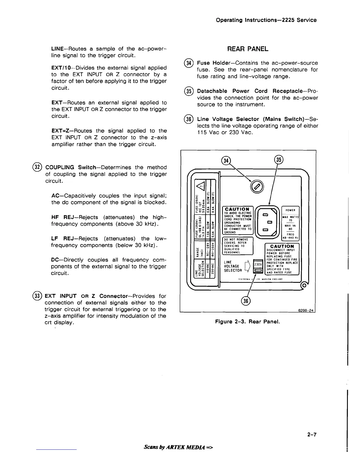
REAR PANEL
@
Fuse Holder-Contains the ac-power-source
fuse. See the rear-panel nomenclature for
fuse rating and line-voltage range.
@
Detachable Power Cord Receptacle-Pro-
vides the connection point for the ac-power
source to the instrument.
@
Line Voltage Selector (Mains Switch)-Se-
lects the line voltage operating range of either
1
15
Vac or 230 Vac.
Figure 2-3. Rear Panel.
Scans
by
ARTEK
MEDLQ
=>
 Loading...