Operating Instructions-2225 Service
OPERATING CONSIDERATIONS
This part contains basic operating information and
techniques that should be considered before
attempting to make any measurements with the
instrument.
GRATICULE
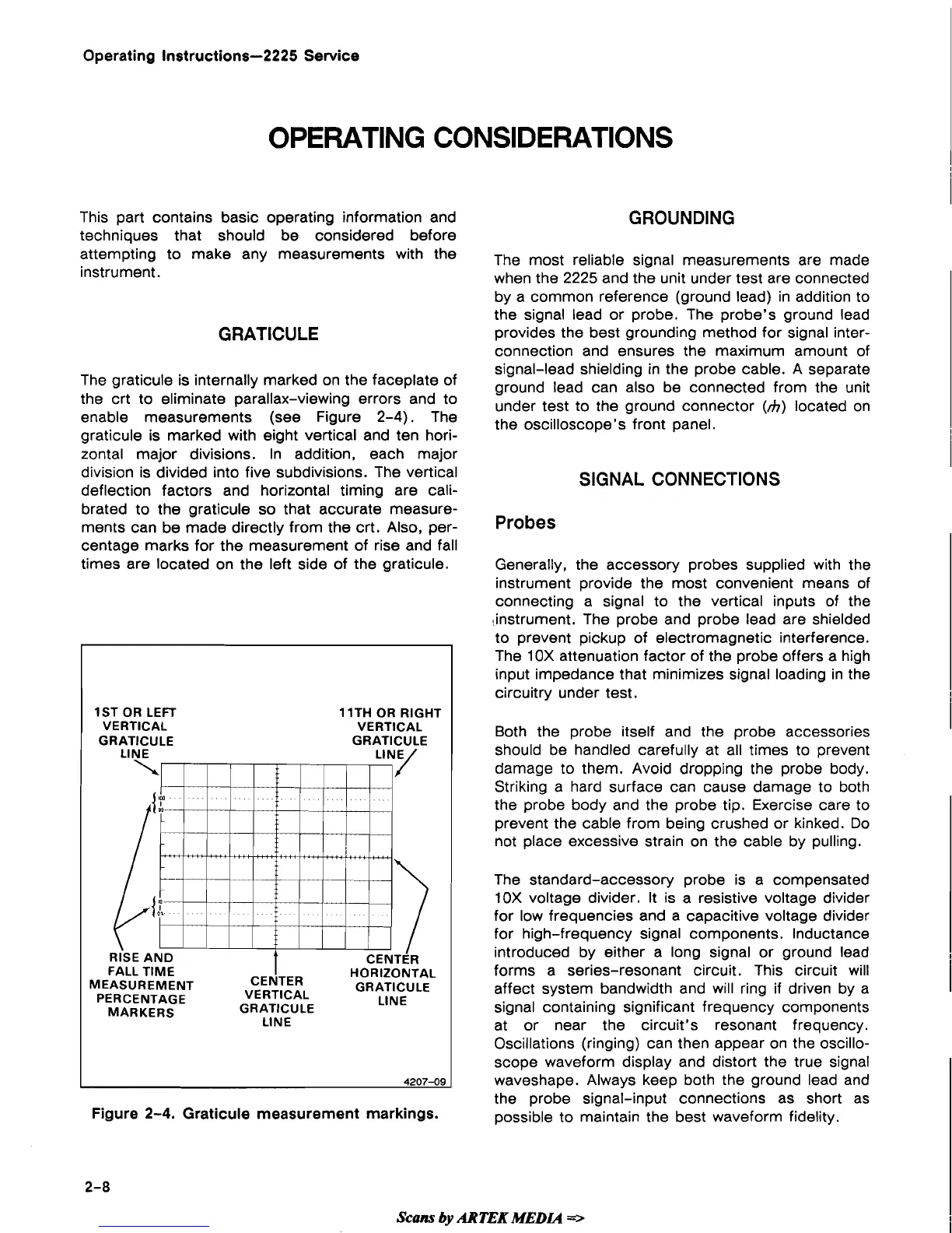
The graticule is internally marked on the faceplate of
the crt to eliminate parallax-viewing errors and to
enable measurements (see Figure
2-4).
The
graticule is marked with eight vertical and ten hori-
zontal major divisions. In addition, each major
division is divided into five subdivisions. The vertical
deflection factors and horizontal timing are cali-
brated to the graticule so that accurate measure-
ments can be made directly from the crt. Also, per-
centage marks for the measurement of rise and fall
times are located on the left side of the graticule.
1ST OR LEFT
1 lTH OR RIGHT
VERTICAL VERTICAL
GRATICULE GRATICULE
FALL TIME
CENTER
HORIZONTAL
MEASUREMENT
VERTICAL
GRATICULE
PERCENTAGE
GRATICULE
LlNE
MARKERS
LlNE
4207-09
GROUNDING
The most reliable signal measurements are made
when the
2225
and the unit under test are connected
by a common reference (ground lead) in addition to
the signal lead or probe. The probe's ground lead
provides the best grounding method for signal inter-
connection and ensures the maximum amount of
signal-lead shielding in the probe cable. A separate
ground lead can also be connected from the unit
under test to the ground connector
(h)
located on
the oscilloscope's front panel.
SIGNAL CONNEC'I'IONS
Probes
Generally, the accessory probes supplied with the
instrument provide the most convenient means
of
connecting a signal to the vertical inputs of the
!instrument. The probe and probe lead are shielded
to prevent pickup of electromagnetic interference.
The 1
OX attenuation factor of the probe offers a high
input impedance that minimizes signal loading in the
circuitry under test.
Both the probe itself and the probe accessories
I
should be handled carefully at all times to prevent
damage to them. Avoid dropping the probe body.
Striking a hard surface can cause damage to both
the probe body and the probe tip. Exercise care to
prevent the cable from being crushed or kinked. Do
not place excessive strain on the cable by pulling.
The standard-accessory probe is a compensated
10X voltage divider. It is a resistive voltage divider
for low frequencies and a capacitive voltage divider
for high-frequency signal components. Inductance
introduced by either a long signal or ground lead
forms a series-resonant circuit. This circuit will
affect system bandwidth and will ring if driven by a
signal containing significant frequency components
at or near the circuit's resonant frequency.
Oscillations (ringing) can then appear on the oscillo-
scope waveform display and distort the true signal
waveshape. Always keep both the ground lead and
the probe signal-input connections as short as
Figure
2-4.
Graticule measurement markings.
possible to maintain the best waveform fidelity.
Scans
by
ARTEK MEDIA
=>
 Loading...