Operating Instructions-2225 Service
measurements. Probe compensation is accom-
plished by the following steps:
1.
Preset the instrument controls and obtain a
baseline trace as described in the Initial Setup.
2.
Connect the two
10X
probes (supplied with the
instrument) to the CH
1
OR
X
and CH 2 OR
Y
input connectors.
3.
Connect the Channel
1
probe tip to the PROBE
ADJUST terminal.
4.
Use the CH
1
POSITION control to vertically
center the display. If necessary, adjust the
Trigger LEVEL control to obtain a stable display
on the positive
(1)
SLOPE.
LF
COMP
ROTATING
\
SLEEVE
J
0)
R1
R2
6299-25
NOTE
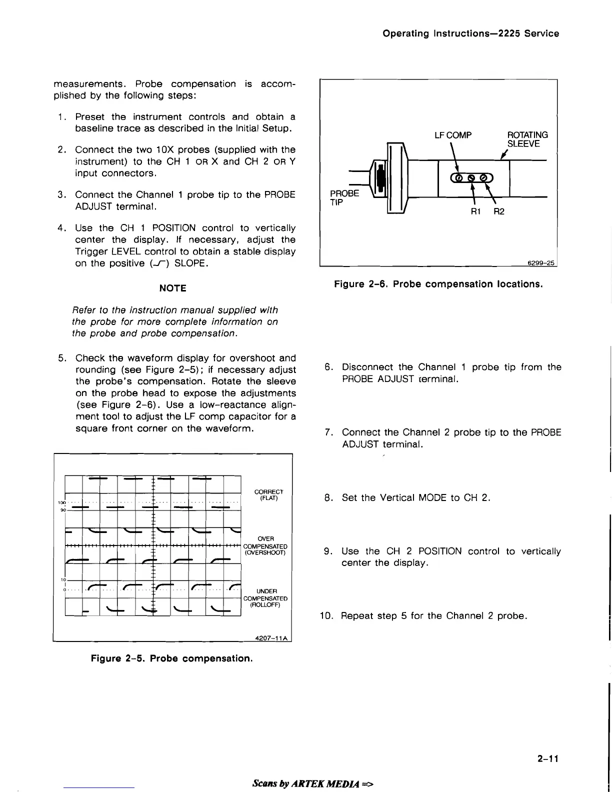
Figure
2-6.
Probe compensation locations.
Refer to the instruction manual supplied with
the probe for more complete information on
the probe and probe compensation.
5. Check the waveform display for overshoot and
rounding (see Figure 2-5);
if
necessary adjust
6.
Disconnect the Channel 1 probe tip from the
the probe's compensation. Rotate the sleeve
PROBE ADJUST terminal.
on the probe head to expose the adjustments
(see Figure 2-6). Use a low-reactance align-
ment tool to adjust the LF
comp capacitor for a
square front corner on the waveform.
7.
Connect the Channel 2 probe tip to the PROBE
ADJUST terminal.
CORRECT
(FLAT)
1
OVER
COMPENSATED
(OVERSHOOT)
UNDER
COMPENSATED
(ROLLOFF)
4207-1
1
A
8.
Set the Vertical MODE to
CH
2.
9.
Use the CH
2
POSITION control to vertically
center the display.
10.
Repeat step 5 for the Channel 2 probe.
Figure 2-5. Probe compensation.
Scans
by
ARTEK
MEDL4
*
 Loading...