Adjustment Procedure-2225 Service
1
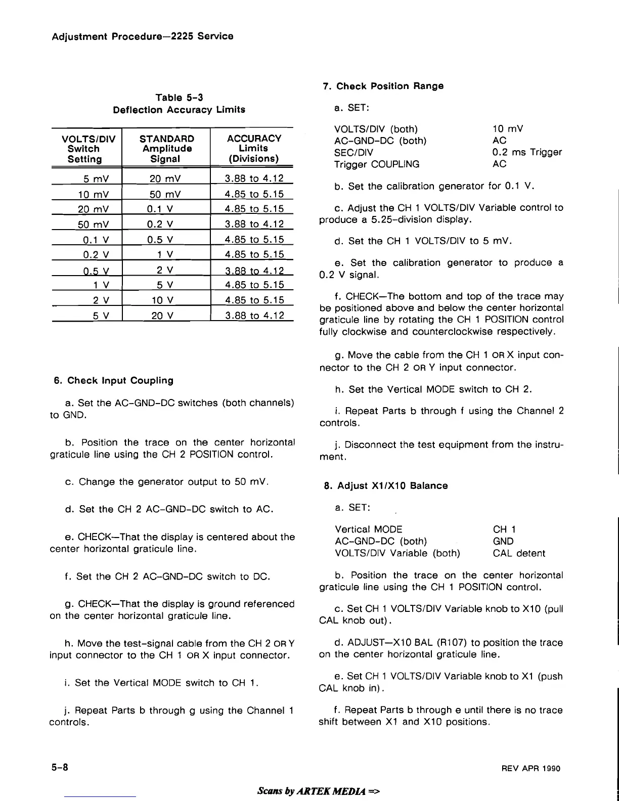
Table
5-3
Deflection Accuracy Limits
6.
Check Input Coupling
a. Set the AC-GND-DC switches (both channels)
to GND.
b. Position the trace on the center horizontal
graticule line using the CH 2 POSITION control.
c. Change the generator output to 50
mV
d. Set the CH 2 AC-GND-DC switch to AC.
e. CHECK-That the display is centered about the
center horizontal graticule line.
f. Set the CH
2
AC-GND-DC switch to DC.
g. CHECK-That the display is ground referenced
on the center horizontal graticule line.
h. Move the test-signal cable from the CH 2
OR
Y
input connector to the CH
1
OR
X
input connector.
i.
Set the Vertical MODE switch to CH
1.
j.
Repeat Parts b through
g
using the Channel
1
controls.
7.
Check Position Range
a.
SET:
VOLTSIDIV (both)
10
mV
AC-GND-DC (both) AC
SECIDIV
0.2 ms Trigger
Trigger COUPLING
AC
b. Set the calibration generator for
0.1
V.
c.
Adjust the CH
1
VOLTSIDIV Variable control to
produce a 5.25-division display.
d. Set the CH
1
VOLTSIDIV to
5
mV.
I
e. Set the calibration generator to produce a
0.2 V signal.
I
f. CHECK-The bottom and top of the trace may
I
be positioned above and below the center horizontal
graticule line by rotating the CH
1
POSITION control
fully clockwise and counterclockwise respectively.
g. Move the cable from the CH
1
OR
X
input con-
nector to the CH 2
OR
Y
input connector.
h. Set the Vertical MODE switch to CH 2.
I
i.
Repeat Parts b through f using the Channel 2
controls.
j.
Disconnect the test equipment from the instru-
ment.
8.
Adjust
XllXlO
Balance
a. SET:
Vertical MODE CH
1
AC-GND-DC (both) GND
VOLTSIDIV Variable (both) CAL detent
b. Position the trace on the center horizontal
graticule line using the CH
1
POSITION control.
c. Set CH
1
VOLTSIDIV Variable knob to
XI0
(pull
CAL knob out).
d. ADJUST-XI
0
BAL
(R107)
to position the trace
I
on the center horizontal graticule line.
e. Set CH
1
VOLTSIDIV Variable knob to
X1
(push
CAL knob in).
f.
Repeat Parts b through e until there is no trace
shift between
XI
and
XI0
positions.
Scam
by
ARTEK
MEDLa
=>
REV
APR
1990
 Loading...